question

captnsnap avatar image
captnsnap asked

GX control of MPPT

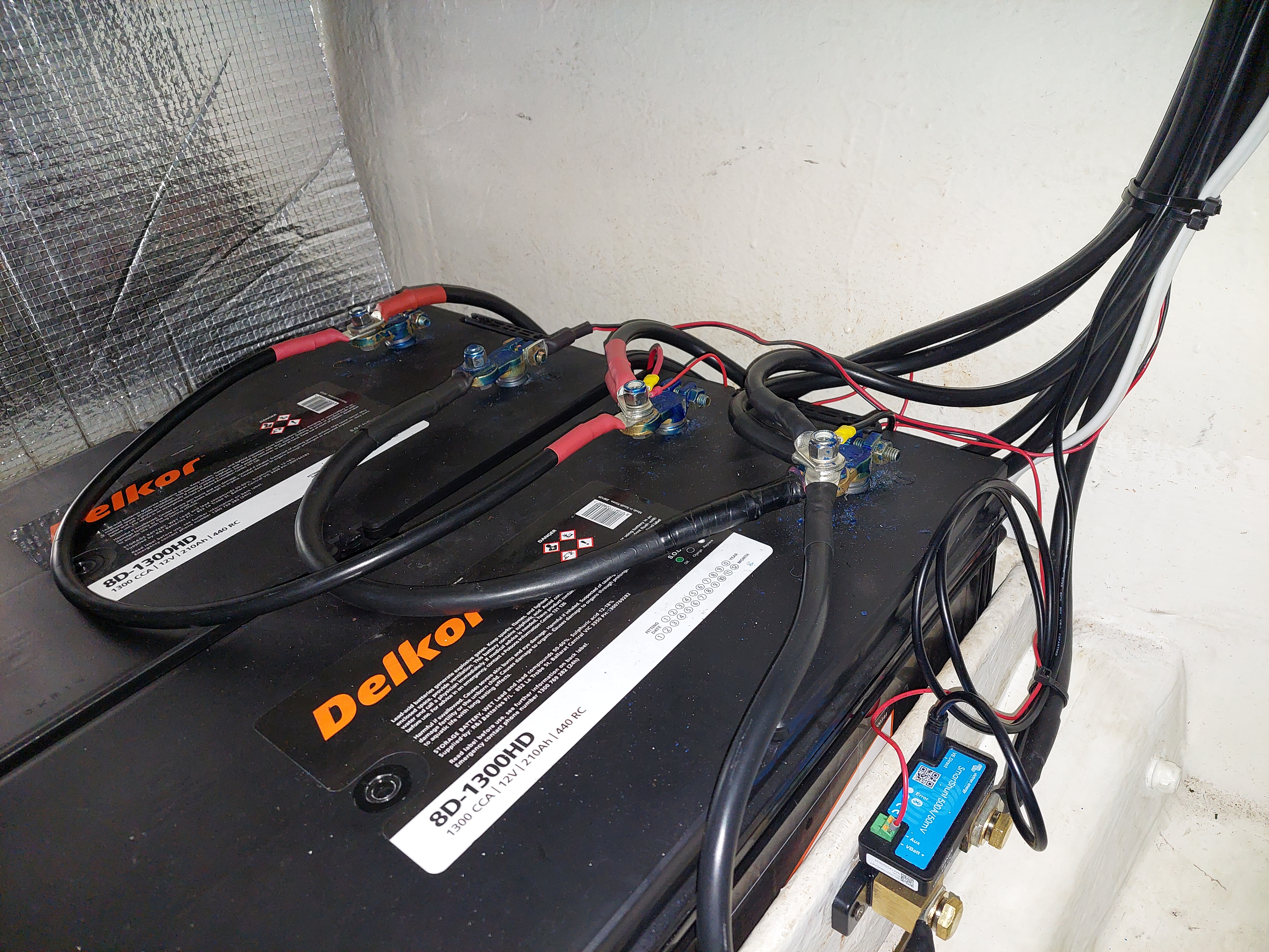
I have read numerous posts on this issue, but need some clarification. Our setup is Multiplus II, Smartshunt on the House Bank of Lead Acids, 100/50 Smartsolar MPPT managing 480watts of PV, Cerbo GX and GX Touch 50. Twin Orions will join the party when the new engines go in later this year, at which time we will probably convert house bank to Lithium.

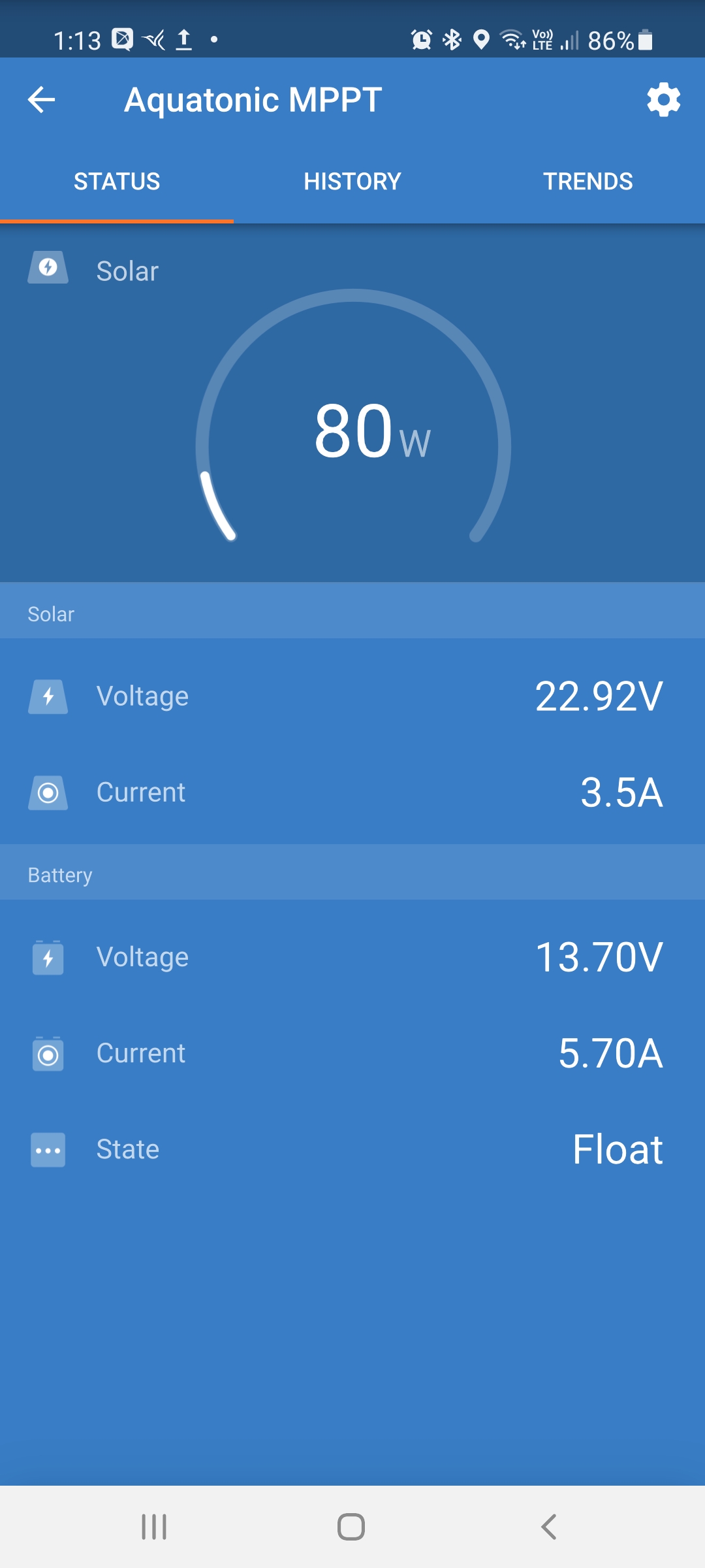
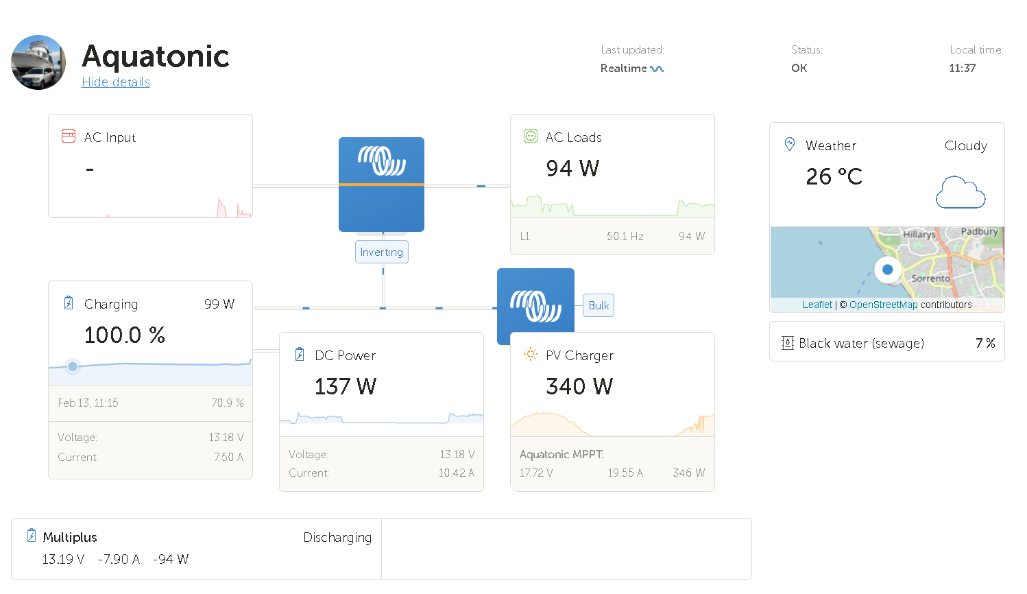
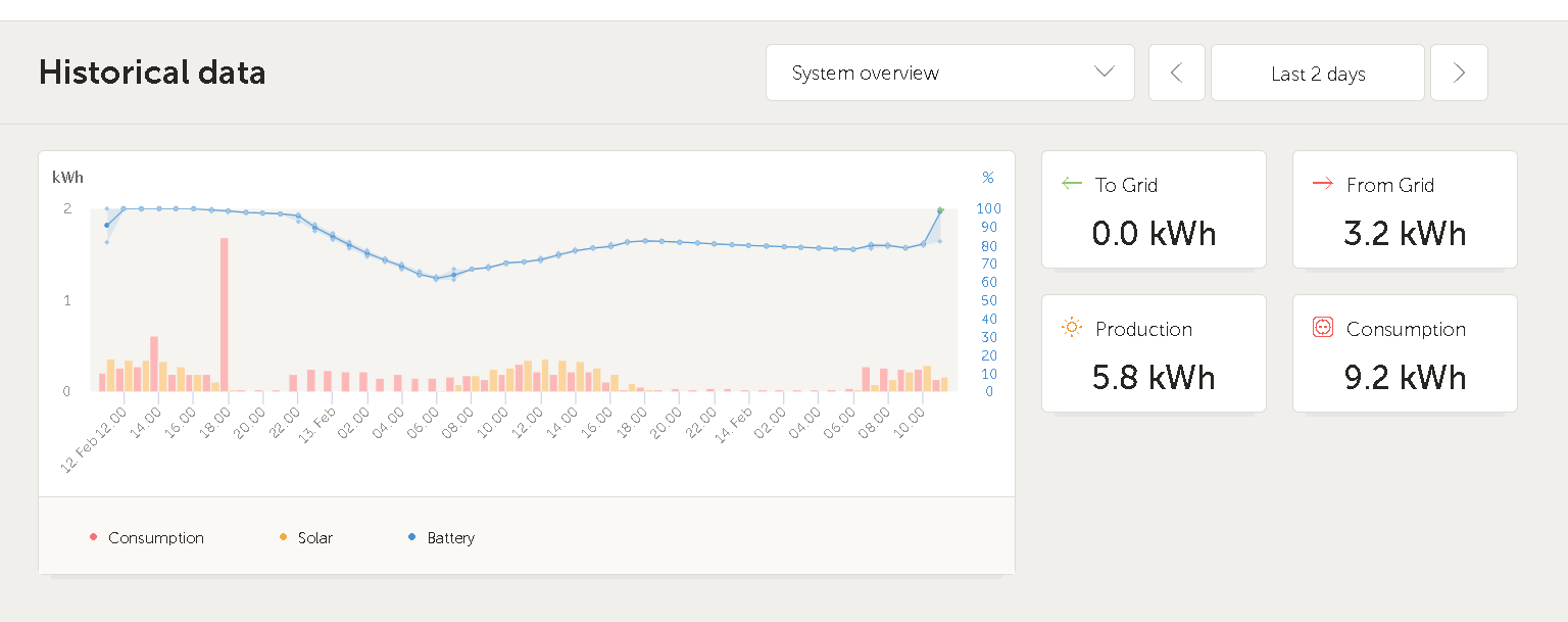
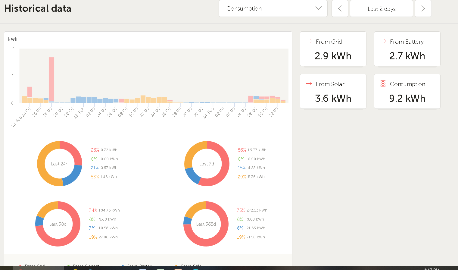
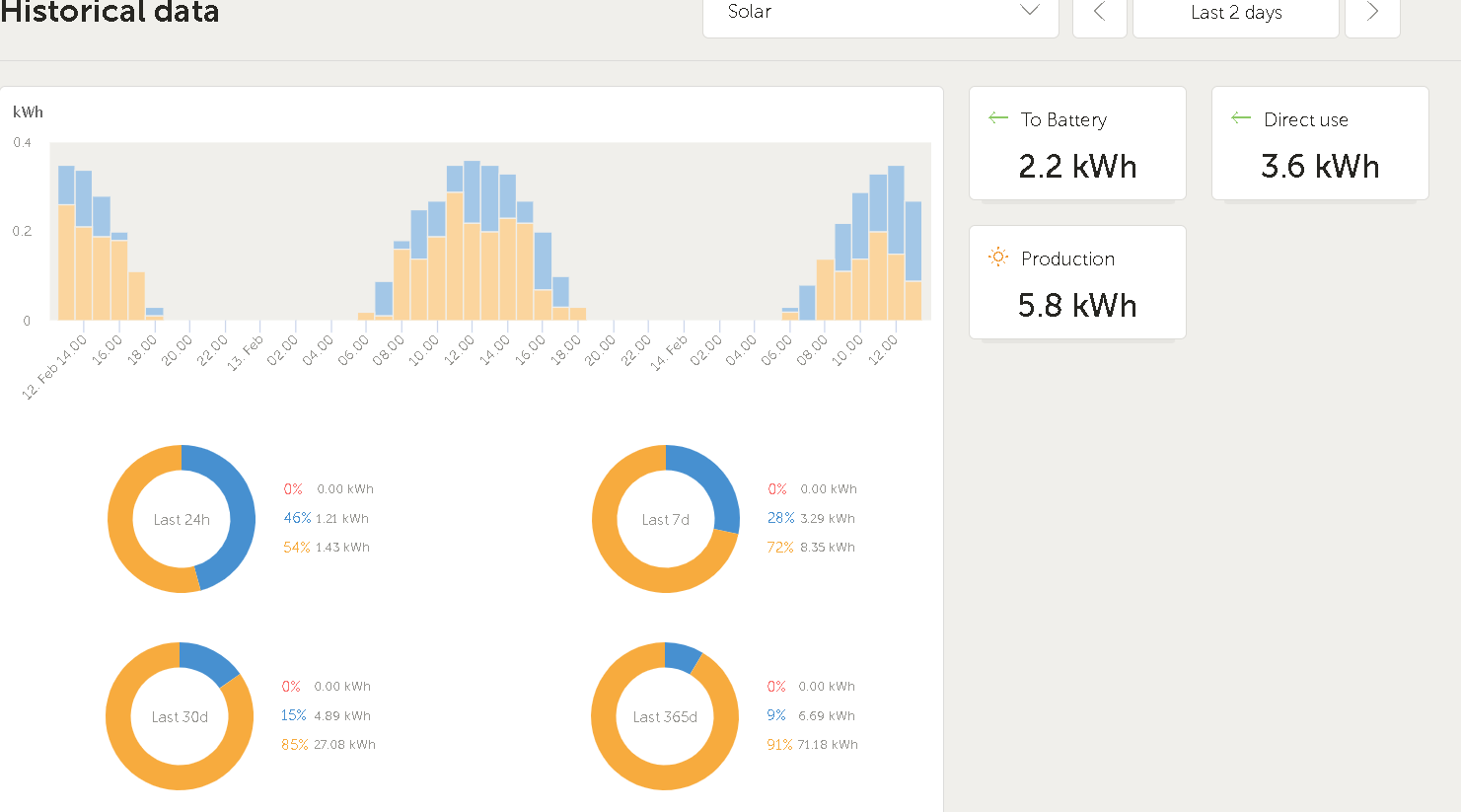
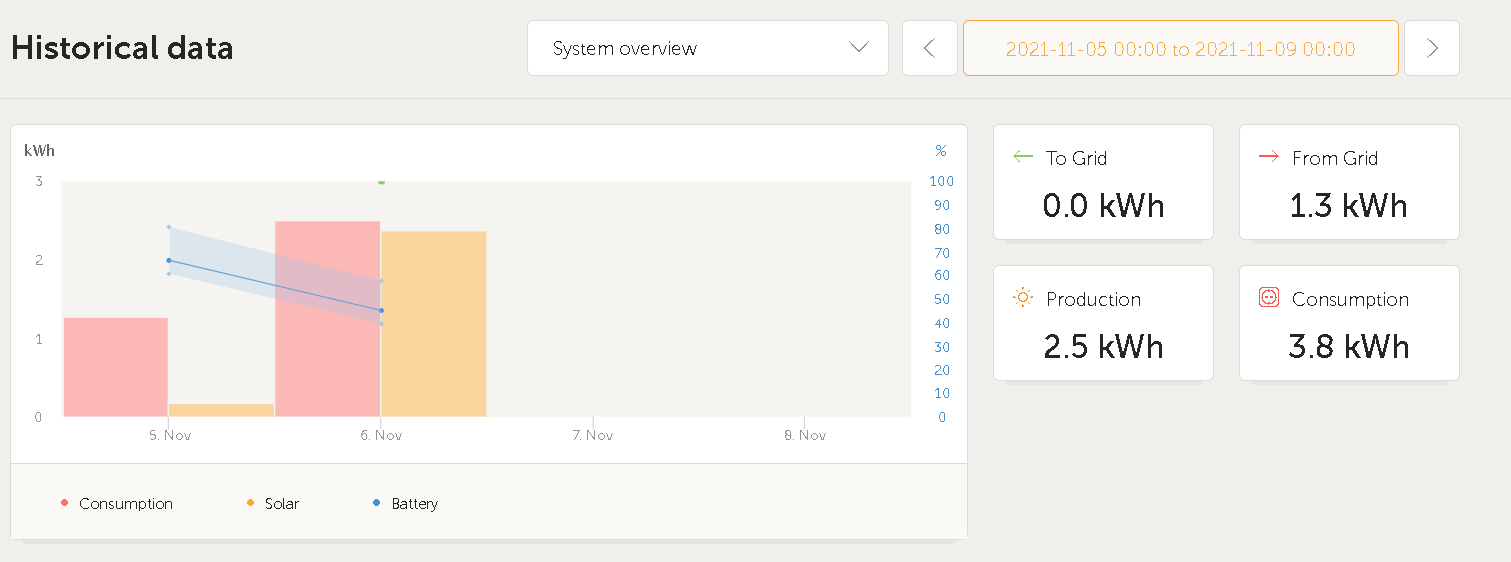
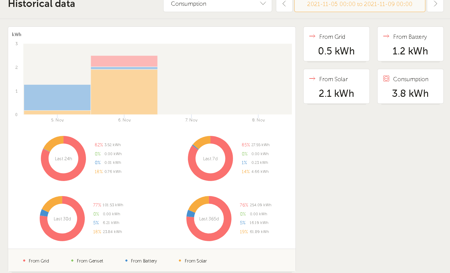
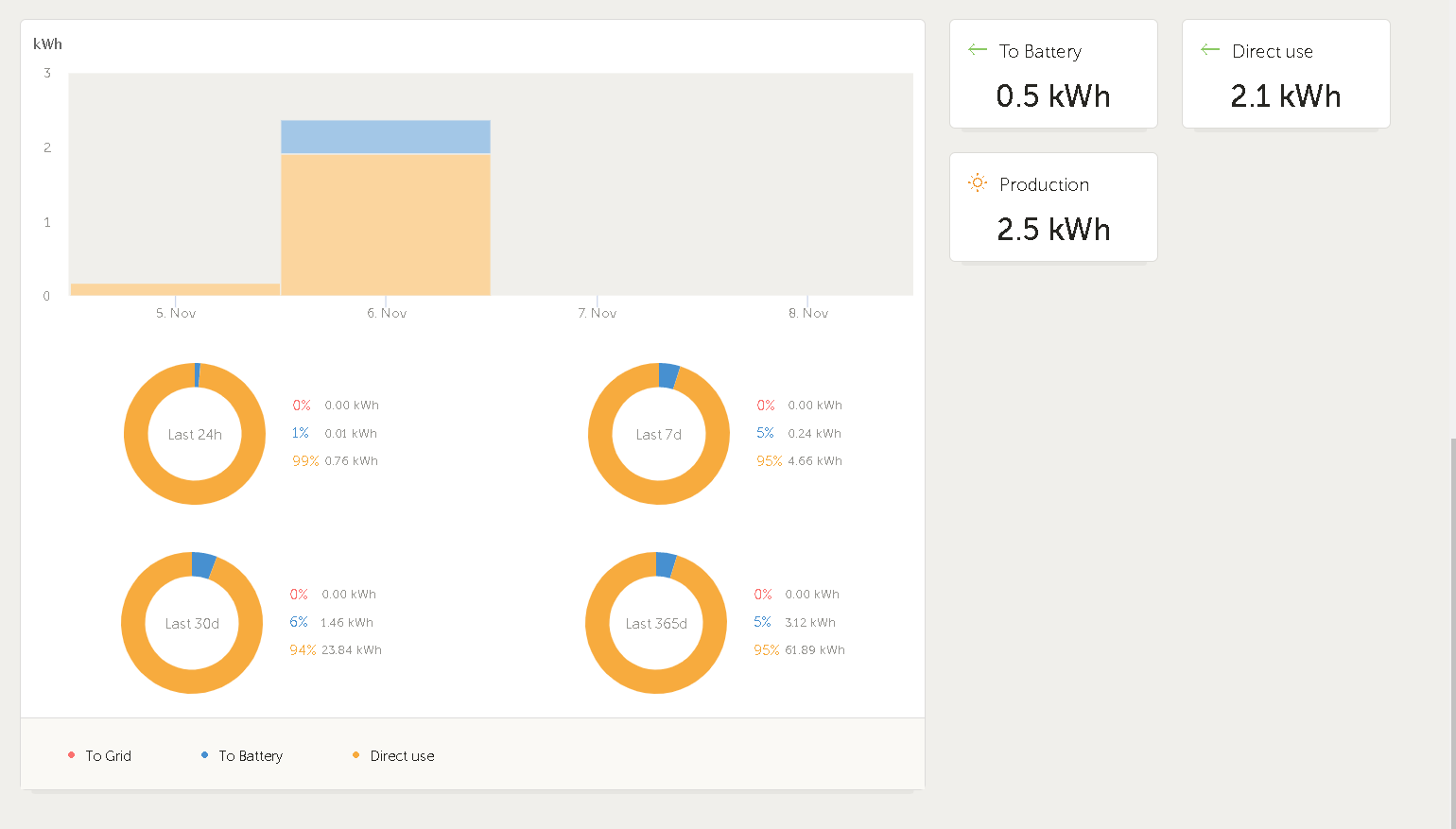
My issue it has been for many people before, is that the MPPT happily dawdles along in "Float" or at very low power input even as the battery SoC dwindles. The boat is in a pen under Shorepower AC input most of the time. Day-trips are common and not an issue as the drain on the batteries is minimal and Shorepower takes over as soon as she gets back to the pen. But if we are away for a few days, the battery gradually drains down, and is often too low for the PV system to recover once they finally awake from their stupor. See the following for 4 days away in very sunny conditions:

1644108819211.png

1644108799223.png

1644108643416.png

My understanding is we need to tweak the settings to allow the Multiplus or Cerbo to determine the charging behaviour. Is this the solution?

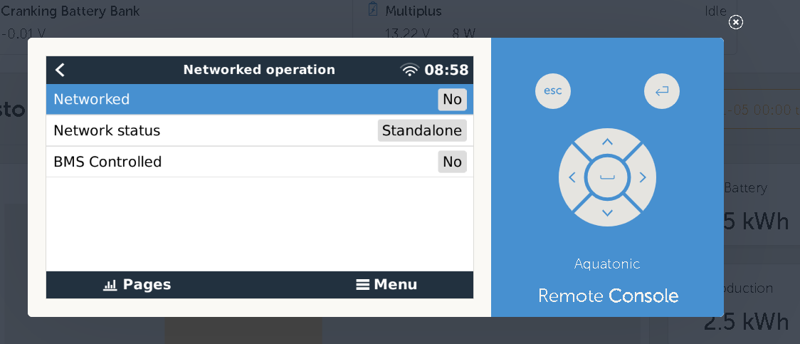
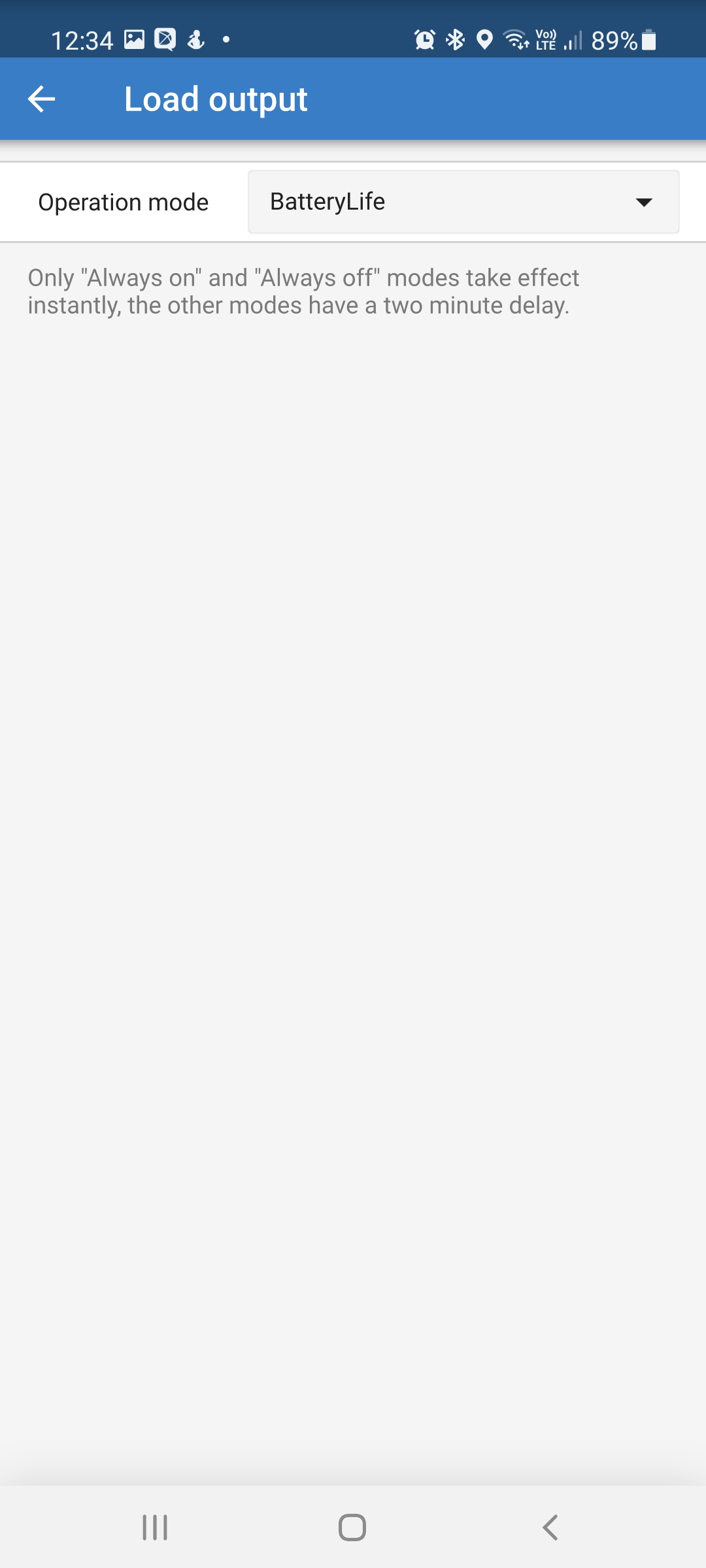
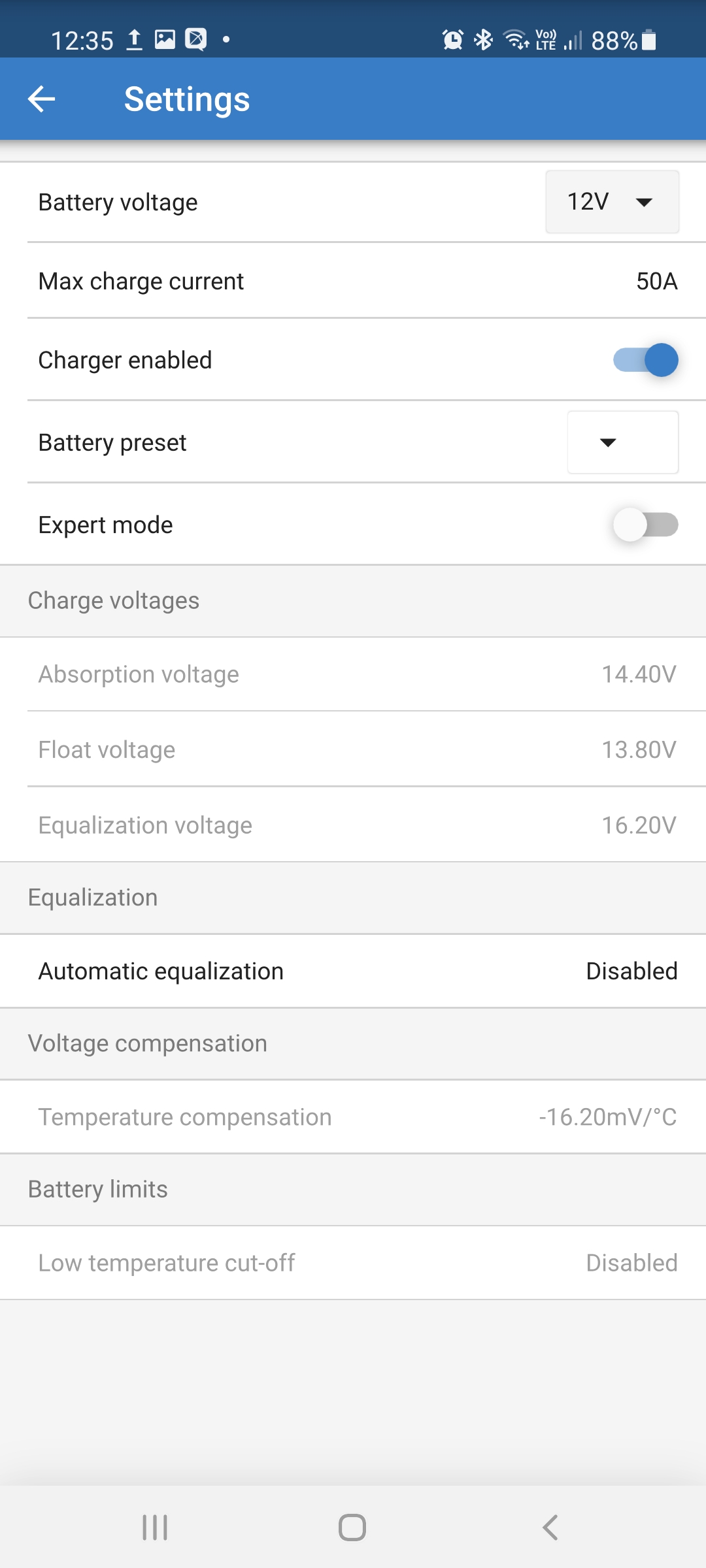
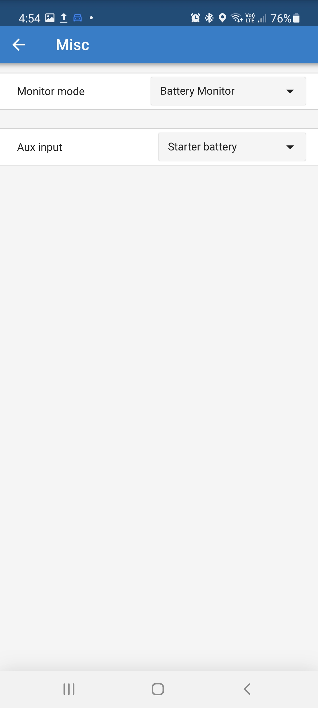
If so, can someone help me with exactly which settings to change on which device? Do I start with this in the MPPT settings on the GX Touch?:

1644109183504.png


MPPT Controllerscerbo gx
1644108643416.png (38.5 KiB)
1644108799223.png (45.2 KiB)
1644108819211.png (22.3 KiB)
1644109183504.png (51.8 KiB)
5 comments
2 |3000

Up to 8 attachments (including images) can be used with a maximum of 190.8 MiB each and 286.6 MiB total.

snoobler avatar image snoobler commented ·

This really sounds like a case of consumption exceeding PV production or an improperly configured system.


Please link your MPPT settings.


Do you receive exceptional sun? No clouds or shading of any kind from sunrise to sunset?

0 Likes 0 ·
captnsnap avatar image captnsnap snoobler commented ·
Perth WA does have exceptional sunshine, but there was some cloud on the first two days. I am heading down the boat and so can get the MPPT settings directly. Have not worked out how to access/change them from VRM portal yet.
0 Likes 0 ·
snoobler avatar image snoobler captnsnap commented ·

You can use Victron Connect to access the GX device. From there, you can access VE.Direct connected devices:


1644115646706.png


Click on the GX and then select the MPPT from the list:

1644115682045.png


0 Likes 0 ·
1644115646706.png (24.8 KiB)
1644115682045.png (43.3 KiB)
klim8skeptic avatar image klim8skeptic ♦ snoobler commented ·
Victron connect has come a long way :).
0 Likes 0 ·
kevgermany avatar image kevgermany ♦♦ commented ·
Some of the MPPTs have a pair of load terminals. I haven't researched it, but it may resolve your issues.
0 Likes 0 ·
12 Answers
Wayne avatar image
Wayne answered ·

Hi @CaptnSnap it sounds like you would benefit from setting up DVCC in the GX in short you program the MP to the charge profile required, in the GX set the Shunt as the system SoC and voltage, this then tells the MPPT's to ignore there programed profile and read voltage and current and instead they use the data direct from the shunt. Strongly suggest having a read up on DVCC before implementing. I also use it in my system to control max charge current, where at times my system is capable of delivering higher amps than my battery spec recommends, so i enjoy the benefit of the extra in poor conditions and the DVCC throttles when in optimal conditions.

Hope this helps

1 comment
2 |3000

Up to 8 attachments (including images) can be used with a maximum of 190.8 MiB each and 286.6 MiB total.

captnsnap avatar image captnsnap commented ·
Thanks Wayne. Need to do more reading. Have read a lot but starting to get a clearer picture of what I need to do.
0 Likes 0 ·
snoobler avatar image
snoobler answered ·

@Wayne are you certain about this? "ignore their programmed profile"? I don't think that's the case. They will still use their programmed profile, but they will use shared voltage/temperature for better accuracy. As you state, DVCC offers a max charge current, which is very useful for lead-acid as they often can't handle the total current the chargers may deliver. I use this as well.


2 comments
2 |3000

Up to 8 attachments (including images) can be used with a maximum of 190.8 MiB each and 286.6 MiB total.

Wayne avatar image Wayne commented ·

Hi @snoobler

Section 8.3 covers it

8. DVCC - Distributed Voltage and Current Control (victronenergy.com)

Small insert -

Inverter/charger (applies to MPPTs only)

The MPPTs internal charge algorithm is disabled; instead it's being controlled by a charge voltage setpoint coming from the inverter/charger.

MPPT indicated charge state: Ext. control.

0 Likes 0 ·
pwfarnell avatar image pwfarnell Wayne commented ·

If you look in the table in Section 8.3, this external control only applies with ESS and normal batteries, a boat is not going to be running ESS. For a standard set up with normal batteries the MPTT remains on its internal algorithm. In this situation, DVCC is only sharing voltage, current and temperature readings. This is how my same set up works on a boat.

161fbf7190cd3a.png

0 Likes 0 ·
161fbf7190cd3a.png (71.2 KiB)
snoobler avatar image
snoobler answered ·

Given the OP's use of lead-acid batteries, I think we can assume they're not intelligent.


The concerns now become:

1) does OP have ESS and DVCC enabled thus overriding MPPT settings with inverter/charger settings?

2) does OP have MPPT configured properly.

1 comment
2 |3000

Up to 8 attachments (including images) can be used with a maximum of 190.8 MiB each and 286.6 MiB total.

kevgermany avatar image kevgermany ♦♦ commented ·

ESS shouldn't be used on mobile systems, like boats and campervans. MPPT should be configured correctly as a safety/fallback feature.

0 Likes 0 ·
captnsnap avatar image
captnsnap answered ·

OK settings for MPPT are:


1644209510985.jpeg

1644209535423.jpeg

1644209563867.jpeg


1644210841805.jpeg

I am reading through the MPPT manual and notice that the last screenshot does not have a VE Smart icon top right. Given the MPPT was installed first, could part of the issue be that we have not added it to the Smart Network? All devices appear on the VRM Portal but could it be that we have not set this up properly?


1644209510985.jpeg (141.7 KiB)
1644209535423.jpeg (258.7 KiB)
1644209563867.jpeg (336.6 KiB)
1644210841805.jpeg (243.3 KiB)
2 |3000

Up to 8 attachments (including images) can be used with a maximum of 190.8 MiB each and 286.6 MiB total.

snoobler avatar image
snoobler answered ·

VE.Smart is for bluetooth to bluetooth connections. You should have your smartshunt and MPPT connected to GX via VE.Direct cable. Within the GX device, you enable DVCC and enable shared voltage, temperature (assuming you have smartshunt w/temp sensor) and current source:


1644213424271.png


Where I have circled the BMV, you would select the Smartshunt.


The controller appears to be set mostly correct. The absorption and float values are reasonable.


Please select the expert switch and include those settings.

Please include a photo of the smartshunt installation.

Please include smartshunt settings.


1644213424271.png (45.4 KiB)
2 |3000

Up to 8 attachments (including images) can be used with a maximum of 190.8 MiB each and 286.6 MiB total.

captnsnap avatar image
captnsnap answered ·

The Multi, MPPT and Smartshunt are all connected via VE Direct cables.

Out of interest, I switched DVCC on and went to select temp sensor on Smartshunt (which is definitely connected) and get this screen:


1644222550240.png

Here is the smartshunt wiring PRIOR to the sparky realising that EVERYTHING needs to go through the negative terminal - that has been resolved. But this shows the VE Direct and temp cables in place, so not sure why I cannot select Smartshunt vs Multi.

1644223886624.jpeg

1644224687046.jpeg

1644224781017.jpeg

1644224270508.jpeg


1644222550240.png (53.1 KiB)
1644223886624.jpeg (5.7 MiB)
1644224270508.jpeg (113.1 KiB)
1644224687046.jpeg (294.0 KiB)
1644224781017.jpeg (310.9 KiB)
3 comments
2 |3000

Up to 8 attachments (including images) can be used with a maximum of 190.8 MiB each and 286.6 MiB total.

JohnC avatar image JohnC ♦ commented ·

@CaptnSnap

You need to select the Temp sensor to have it show. Look in Aux Input.

0 Likes 0 ·
kevgermany avatar image kevgermany ♦♦ JohnC ♦ commented ·
Also looks as if the temp sensor is on positive, not negative terminal.
0 Likes 0 ·
snoobler avatar image snoobler kevgermany ♦♦ commented ·

Positive terminal installation is correct.

https://www.victronenergy.com/media/pg/SmartShunt/en/installation.html


HOWEVER, THERE IS NO TEMP PROBE INSTALLED. It's simply the voltage sensing/power wire installed.

0 Likes 0 ·
captnsnap avatar image
captnsnap answered ·

Righto. Selected "temp " in Aux Input and still can't see it so will check that it is connected properly tomorrow. Will I need to reboot anything to set the new settings?

2 comments
2 |3000

Up to 8 attachments (including images) can be used with a maximum of 190.8 MiB each and 286.6 MiB total.

snoobler avatar image snoobler commented ·


No temp probe is installed on SmartShunt. Please procure correct sensor and install.


Multiple wiring problems, though many/all may have been addressed:

1644240996579.png


I assume by your comments that some of these have been resolved with your "sparky." The shunt was bypassed by the three additional wires (two large, one small) on the main negative terminal, i.e., any current coming in or out on those wires is not seen by the shunt. As a result, the SoC will never be accurate and may have been responsible for the perceived disparity in declining SoC even with input.


While you may have listed numbers over a 4 day period, it appears that you use approximately 3.8kWh/day. If consumption is the same when "off grid," then you are simply using more than your panels can deliver. In perfect solar conditions, i.e., panels tilted to your latitude, warmer half of the year, always facing south, not a single sliver of shade on any part of any panel from sunrise to sunset, your panels will might produce about 2.5kWh/day. If panels are mounted horizontally, at this time of year, you will get maybe half that. Even with great solar, you are using more power than the array can replenish.


CAN YOU INCLUDE DASHBOARD OUTPUT FOR ONE OF THESE PERIODS WHERE THE BATTERY IS DEPLETED?


Based on your statement that your batteries are too low for the PV to resume on your multi-day trips, you are using more energy than your solar can replenish in a day, and you are drawing your batteries down each day until empty - which is damaging them. You need to supplement with generator charging.


Your shunt is properly configured for shore charging (consistently available charging). When out on the water with solar only (INconsistently available charging), you may trigger false syncs to 100%. It might be wise to change the charged voltage to 14.1V when not on shore power.

0 Likes 0 ·
1644240996579.png (1.4 MiB)
kevgermany avatar image kevgermany ♦♦ snoobler commented ·

I was wrong, the temp sensor for the multi is on a negative terminal

0 Likes 0 ·
captnsnap avatar image
captnsnap answered ·

You have all been so helpful.

So I activated DVCC and this has absolutely helped to ensure solar carries more of the load. I will sort the temperature probe, and get an up to date image of the install.

In the meantime, I think I just witnessed the false synch to 100%. Once we connected back to shorepower, I was actually watching the SoC at around 82% and wondering why there was not a higher AC contribtion to charging when it suddenly reverted to 100%. Whats interesting is that the solar is still indicating "bulk" input despite SoC being 100%.


1644810260999.png


What I am now interested in is whether this also happened 2 days ago when solar appeared to have returned the batteries to 100% SoC very quickly at around midday. This data appears to suggest that solar is keeping up with drain, but I am starting to wonder if the SoC is accurate based on your comments above.


1644810392201.png


Again, much of this will be fixed once we have twin Orion's installed to the new engines and charging both banks as we go, but in the meantime keen to hear how to tweak this to maximise our capabilities when away from shorepower.


More data:


1644817721283.png


1644817895635.png


Thoughts?


1644810260999.png (123.9 KiB)
1644810392201.png (35.0 KiB)
1644817721283.png (71.8 KiB)
1644817895635.png (45.1 KiB)
2 |3000

Up to 8 attachments (including images) can be used with a maximum of 190.8 MiB each and 286.6 MiB total.

kevgermany avatar image
kevgermany answered ·

SOC will be coming from the BMV. I see your battery voltage just over 13. Guess it's the BMV settings. Maybe attach a screen shot of them.

1 comment
2 |3000

Up to 8 attachments (including images) can be used with a maximum of 190.8 MiB each and 286.6 MiB total.

captnsnap avatar image captnsnap commented ·

1644828696094.jpeg

Is this the screen you are looking for? Is this saying that the system will consider itself at 100% SoC once the voltage hits 13.2? That seems a bit conservative.

Snoobler is this what you are suggesting I change to 14.1V? Is there any harm in leaving it at 14.1 while we are on shorepower? Can see it being something I forget to change back!


0 Likes 0 ·
1644828696094.jpeg (311.6 KiB)
kevgermany avatar image
kevgermany answered ·

That's the culprit. As this is a BMV setting, can't do harm. It needs to be set to absorption or just below.

1 comment
2 |3000

Up to 8 attachments (including images) can be used with a maximum of 190.8 MiB each and 286.6 MiB total.

JohnC avatar image JohnC ♦ commented ·
Let's not brush over this too quickly. Setting the CV near Abs V means that when in Float charge it will never sync. I don't want that, so use 13.25V (48V equiv). Still low, but that's to avoid Temp Comp with warm batts in Float.

It's the Tail that's way too high for 13.2V. Sure the default is 4%, but I use less than that (~3%) to tell my mppt to terminate Abs. My Tail setting is 0.6%, and even then, due to sluggishness of pbs reaction with V under passing cloud, I raised the CDT from 3 min to 5.

Depends on the batts, what charge settings are used, Temp Compensation, and personal preference. Also, how good an SOC you want..


0 Likes 0 ·
snoobler avatar image
snoobler answered ·

Per my last post, I recommend you change the BMV charged voltage to 0.3V below absorption when on solar and 0.3V below float on shore. If you don't want to worry about changing it, use absorption. IMHO, it's more important to know what your SoC is when you DON'T have shore available.


This chart:


1644844923829.png


...confirms you are outpacing your solar and is very unhealthy for your batteries. I would get the Orions online sooner rather than later.


1644844923829.png (33.3 KiB)
2 |3000

Up to 8 attachments (including images) can be used with a maximum of 190.8 MiB each and 286.6 MiB total.

captnsnap avatar image
captnsnap answered ·

OK, can a clarify Snoobler that you are saying change Charge Voltage on SmartShunt settings to 14.1V when relying on solar (given current Absorption is 14.4V) and 13.5 when on Shorepower (given Float setting is 13.8)

Guess it wont hurt to change it to 13.5 now and see what happens next time we are out of the pen? Can change it n the fly when we are out and about.

Orions can't be installed until the new engines and 12V alternators get installed once they arrive from Europe (November!)

We have contemplated adding some temporary solar panels for when she is on a weekender etc, but I am starting to wonder whether a 400watt wind generator might be better. Bloody windy here in Perth so suspect that might fill a bit of a gap in power production overnight and add to the 480watt of potential solar generation during the day.

The Orions will dump 100 amps into the system while the engines are running so the batteries should be nicely topped up on our way too and from our destination but if we stay a few days and dont move, we will be relying on solar, wind or the genset to keep us in the game.


1 comment
2 |3000

Up to 8 attachments (including images) can be used with a maximum of 190.8 MiB each and 286.6 MiB total.

snoobler avatar image snoobler commented ·
If charging on solar, and you have your charged voltage set to 13.5V, you will likely generate a false sync where the SoC will read 100% when it is not 100%. I would personally not want to think that I have 100% when it's not 100% when I'm limited to solar power.


If you want to live with one number, then I would stick with 14.1V to avoid a false reading while off shore power.


You either need to cut your consumption or increase production.


Wind can be effective. I would find one in person and assess the noise level. They can be quite unpleasant.

0 Likes 0 ·