question

Topper avatar image
Topper asked

ESS not inverting when grid fails

I have configured the following components in an ESS solution;

- Quattro 24/8000/200
- Victron lithium battery 25.6V/200Ah Smart-a
- VE.Bus BMS
- Solaredge SE5000 on AC-Out L1

Everything works well, however the Solaredge has not been able to charge the battery in recent days due to too little sunlight and the low battery message is now visible.


low-battery-1.jpg


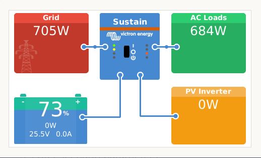
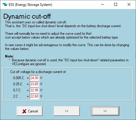
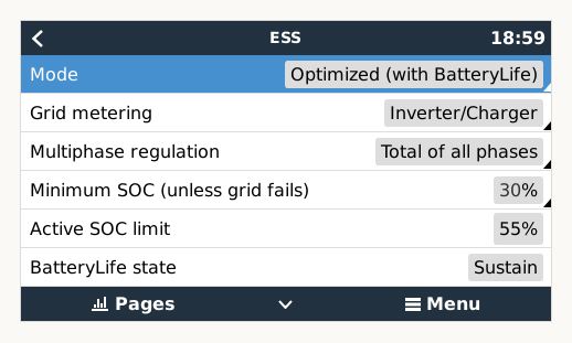
The SOC value is around 73% and when we disconnect the grid the inverter does not turn on, this should not be possible with an ESS configuration when the SOC is higher than the minimum specified value of 30%, see overview of set ESS values.


low-battery-2.jpg

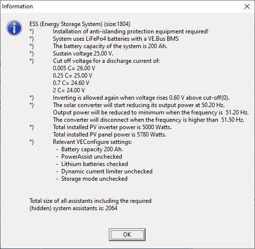
The following values are set in the ESS assistant.


ve-config-final-8.jpg


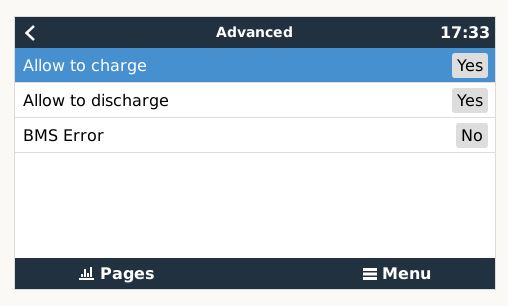
Can someone explain why I get the low battery warning while the VE.BMS still thinks it's all good and why doesn't the inverter turn on when the grid goes down?


Thanks in advance

MultiPlus Quattro Inverter ChargerESSlow battery warning
low-battery-1.jpg (29.1 KiB)
low-battery-2.jpg (36.2 KiB)
2 |3000

Up to 8 attachments (including images) can be used with a maximum of 190.8 MiB each and 286.6 MiB total.

8 Answers
Matthias Lange - DE avatar image
Matthias Lange - DE answered ·

In my opinion the cut-off settings are to high for a lithium batteries. If you look at some recommend settings for other lithium batteries from the compatibility list (BYD for example) you should set all to the same value. I would say 23.5V (the 48V BYD value dividend by 2).

But I'm not 100% sure because we never use Victron batteries for ESS because they are to expensive for that.

2 |3000

Up to 8 attachments (including images) can be used with a maximum of 190.8 MiB each and 286.6 MiB total.

seb71 avatar image
seb71 answered ·

Looks like the battery voltage went below the cut-off voltage and because of that the Quattro is not inverting. Battery voltage "trumps" SOC indicated value.


Not sure why SOC and battery voltage appear to be missaligned.


What do you have under Settings - System Setup - Battery monitor?


Also how are the cell voltages?

2 |3000

Up to 8 attachments (including images) can be used with a maximum of 190.8 MiB each and 286.6 MiB total.

Topper avatar image
Topper answered ·

@Seb71 , thanks for your reply, the setting is under Settings - System Setup - Battery monitor are;

ccgx-3.jpg

As indicated, a VE.Bus BMS is connected to the battery and this is visible under the Device list - Quattro 24/8000/200-2x100, see next image.
ccgx-1.jpg
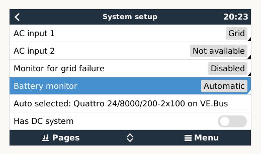
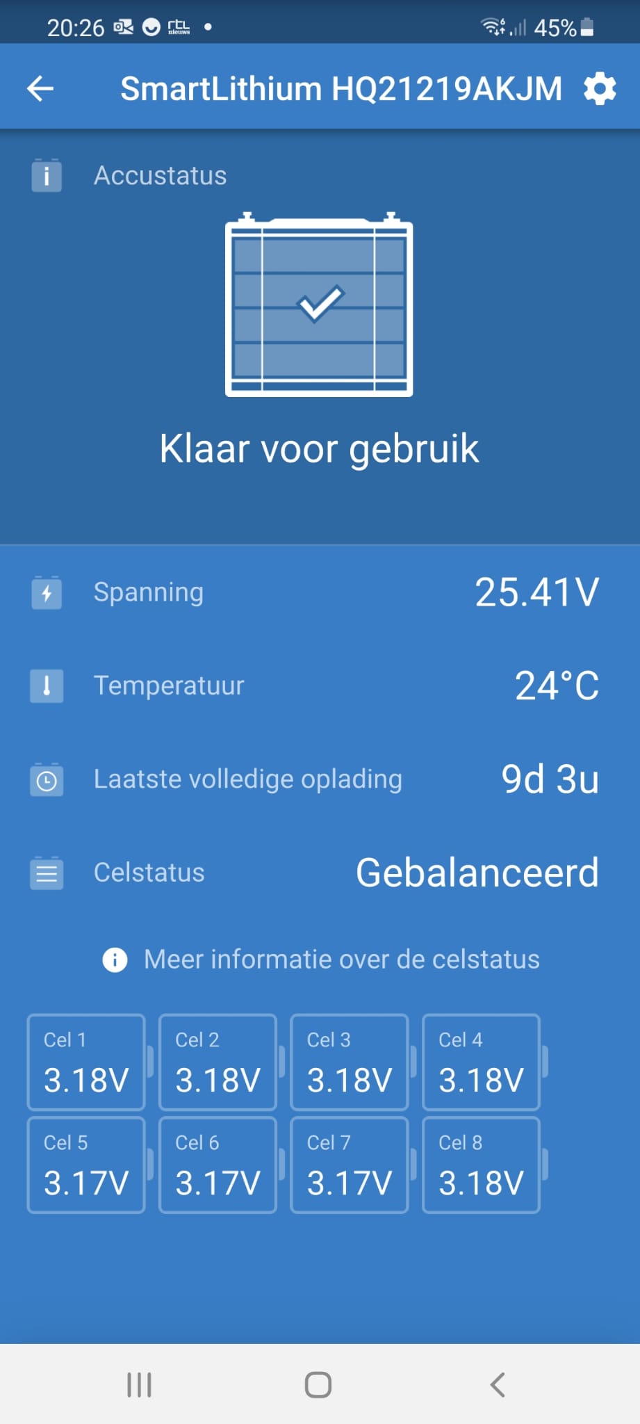
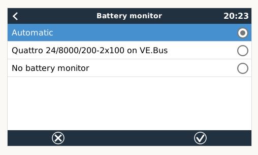
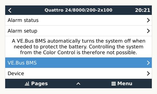
I therefore assume that the battery monitor chosen is the VE.Bus BMS. The following battery overview can be seen from the Victron Connect app.

battery-state.jpg

So it seems that the battery is certainly not empty yet.


ccgx-3.jpg (35.5 KiB)
ccgx-1.jpg (37.1 KiB)
battery-state.jpg (102.8 KiB)
2 |3000

Up to 8 attachments (including images) can be used with a maximum of 190.8 MiB each and 286.6 MiB total.

tnt369 avatar image
tnt369 answered ·


Okay, i check the battery data. Its LiFePO4, the nominal cell voltage is 3.2V.
The sustain voltage is 25.6V. Cut-off Voltage should be around 22-23V.

3 comments
2 |3000

Up to 8 attachments (including images) can be used with a maximum of 190.8 MiB each and 286.6 MiB total.

tnt369 avatar image tnt369 Matthias Lange - DE ♦ commented ·

You are right, I have corrected the above information

0 Likes 0 ·
Topper avatar image Topper tnt369 commented ·

@Matthias Lange - DE thanks for your answer, can i use the following values for the cut-off configuration (just to be sure)?

0.005 C = 24.00 V
0.25 C = 23.65 V
0.7 C = 22.95 V
2C = 22.6 V

these values are still within the limits of the battery values

0 Likes 0 ·
seb71 avatar image
seb71 answered ·

I therefore assume that the battery monitor chosen is the VE.Bus BMS.

It's the Quattro inverter.

If you click on Battery Monitor - Automatic, what options do you have?


I think that if you add a SmartShunt, you will get better results (better SOC monitoring).

-------

The cells seem to have relatively close voltages.


So it seems that the battery is certainly not empty yet.

Not empty, but at one point the battery voltage was under the dynamic cut-off voltage for the load (current draw from the battery) you had at that time.

Keep in mind that under load there is a battery voltage drop. Once the load is gone, the battery voltage rises back a little.

If the battery voltage goes under the cut-off voltage, the system enters "Sustain" mode. In your case the Sustain voltage is 25V. To exit Sustain mode, the battery voltage must rise 0.4V above Sustain level. So in your case it would be 25V+0.4V=25.4V.

2 |3000

Up to 8 attachments (including images) can be used with a maximum of 190.8 MiB each and 286.6 MiB total.

seb71 avatar image
seb71 answered ·

To sum it up: the voltages are fine.

The SOC is wrong.

2 |3000

Up to 8 attachments (including images) can be used with a maximum of 190.8 MiB each and 286.6 MiB total.

Topper avatar image
Topper answered ·

@Seb71 , the following options are under Battery Monitor - Automatic;

ccgx-2.jpg
I can't choose specific the VE.Bus BMS.


ccgx-2.jpg (24.4 KiB)
2 comments
2 |3000

Up to 8 attachments (including images) can be used with a maximum of 190.8 MiB each and 286.6 MiB total.

seb71 avatar image seb71 commented ·
VE.Bus BMS only monitors voltages.


As I wrote, for a more accurate SOC monitoring, add a SmartShunt.

At 25.5V, under no load, that battery in no way has a SOC of 73%.


0 Likes 0 ·
nickdb avatar image nickdb ♦♦ commented ·
The VE BMS does not seem to provide SOC data so the system is defaulting to the inverter to estimate the SOC. In ESS environments, the internal mechanism for calculating the SOC inside the multi/quattro can be quite inaccurate and subject to drift.


An external shunt will be a much more accurate option in this case, and will make sure the system SOC synchronises properly.

SOC seems a fairly basic function of a BMS, so not sure why the VE BMS doesn't provide it.

0 Likes 0 ·
Topper avatar image
Topper answered ·

Thank you all for the replys, I have now set the cut-off values in the ESS configuration as follows and after restarting the low battery message was gone.

ve-config-final-4-jan-2021.jpg


I've read the documentation of the VE.Bus BMS and apparently this BMS can only pass the following things;


Allow-to-charge Yes/No

Allow-to-discharge Yes/No

So no SOC information or temperature measurement from the battery is passed to the Quattro. See BMS status in the CCGX;

bms-ccgx-1.jpg

The Quattro will do the calculation itself for the SOC value of the battery and since it has not been really sunny in recent weeks, it will not be very accurate. Hopefully it will be a bit sunnier in the coming weeks so that the battery is charged better


1 comment
2 |3000

Up to 8 attachments (including images) can be used with a maximum of 190.8 MiB each and 286.6 MiB total.

seb71 avatar image seb71 commented ·

Wrong "solution". You should avoid going under 3.0V cell voltage when discharging (and above 3.6V when charging).

Your problem is the SOC value, not the voltages.


I've read the documentation of the VE.Bus BMS and apparently this BMS can only pass the following things;


Allow-to-charge Yes/No

Allow-to-discharge Yes/No

So no SOC information or temperature measurement from the battery is passed to the Quattro.


I told you that VE.Bus BMS only monitors voltages.


The Quattro will do the calculation itself for the SOC value

I already told you that.


You don't want the battery discharge to be stopped by low battery (or cell) voltage. You want to be stopped when the Minimum SOC (set in ESS) is reached.

For proper SOC monitoring, you need a SmartShunt.

0 Likes 0 ·