Having spent a day reading the specification, There are several alarming conclusions that I have come to with respect to installing a typical 3 phase Victron system based on a Lynx power-in / distributor system, and for example Pylontech batteries.
The basic conclusion is that the typical Victron system recommendation does not comply with this standard, an modification of the layout to make it comply is dangerous to the health of the Victron gear.
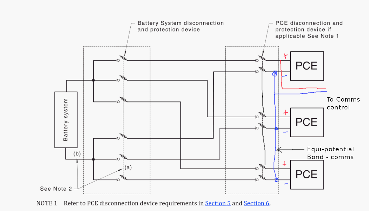
The main culprit is of course the standards requirement for fusing and switching in ALL poles of the supply to each inverter – Where as Victron specify that the negative connection from the inverter to the DC bus be a ‘BOLTED’ connection – no switch, no fuse:-
•It is essential the negative battery terminal between the units is always connected. A fuse or circuit breaker is not allowed.
Personally, I agree with Victron on this issue, and feel that the standard is mis-directed in specifying this for ISOLATED inverters.
The problem also arises as there are no 2 pole DC switches that are “early make / late break” on one pole. This would solve part of the problem, as the early make pole would be used for the negative, and the fusing issue can be solved by making the negative fuse significantly larger than the positive fuse. This battery disconnect with early make on the negative could also be provided by a module within the inverter, however this needs to ba accessible and load break rated. However, the standard then goes on to shoot his concept down by specifying that switch disconnectors must be of the non-polarised type. Placing an early make requirement on the negative pole of the switch automatically polarises the switch. The requirement for a non polarised switch is possibly redundant – suitably qualified personnel – required by the standard- should be able to get positive and negative sorted out. The specification should also allow the “All Poles” rule to be superseded by manufacturer's instructions.
Cause of Damage: If the positive pole makes first, the main capacitors will try to charge through the VE Bus ground, destroying the VE bus interface and anything connected to it. Whilst the VE-Direct interface is an isolated interface, the VE-bus, VE-can and Can interfaces carry a ground reference signal, and are not isolated. Thus connecting a positive main (12,24 or 48V) to a Victron device using one of these interfaces before the negative is connected has the potential to totally destroy your communications system and control boards – effectively writing off the installation.
Can this issue be resolved by using the remote Volt sensing / pre-charge input? No.
The remote sensing measures 5.6 ohm to the corresponding battery terminal, so the coms board ground will jump to V Bat / 2 (6,12,24V) when the precharge is connected, with the potential to cause similar destruction to the comms.
On a lesser issue, the Lynx power in could do with the option of fusing both in the positive and negative bus, this would be ideal if the fuses were in a with-drawable carrier (does not need to be a load break). Whilst this would not be needed with the Pylontech system, other battery modules and individual cells may not be fused, and this would be a good place to put the fusing in a parallel battery system. Battery MBS systems have isolated coms for the battery module boards, and the central Bms can be ground referenced to the main DC bus. The Lynx distributor could also do with fuses or removable links in the negative pole to help comply with the AS/NZ standard.
Other Equipment: Solar Chargers. Whilst there is no big issue with the VE direct coms solar chargers, there are issues with chargers using VE-Can bus as an interface. The latter again will need a permanently bonded negative. The only other requirement that the standard places on installations with solar chargers is that of the increased “Decisive Voltage Classification” (DVC) .As Victron solar chargers are non – isolated (to the best of my knowledge), the SYSTEM DVC is increased to that of the open circuit string voltage. Two modules in series (assuming Voc of 45v) will place you in DVC B and 3 will place you in DVC C. This leads to increased insulation requirements on the DC system terminals – way above what would normally be required for any 48V system. The possible destruction of the solar charge controller by removing the battery connection before removing the PV connection can be addressed by the system shut down procedure. It would also be possible to link a trip into the PV breaker if a battery fuse or breaker trips.
Whilst this is my take on what seems to be an overly onerous specification, I’m open to other views about how to make manufacturer’s recommendations comply with installation specifications. There is some work that Victron could do to ease the problems and improve their products thereby, but the main aim is to get the INSTALLERS who have to certify these installations to complain to the standards council members. By concerted action, the standards can be prevented from disconnection from reality.