question

assyntdavid avatar image
assyntdavid asked

low battery charge efficiency

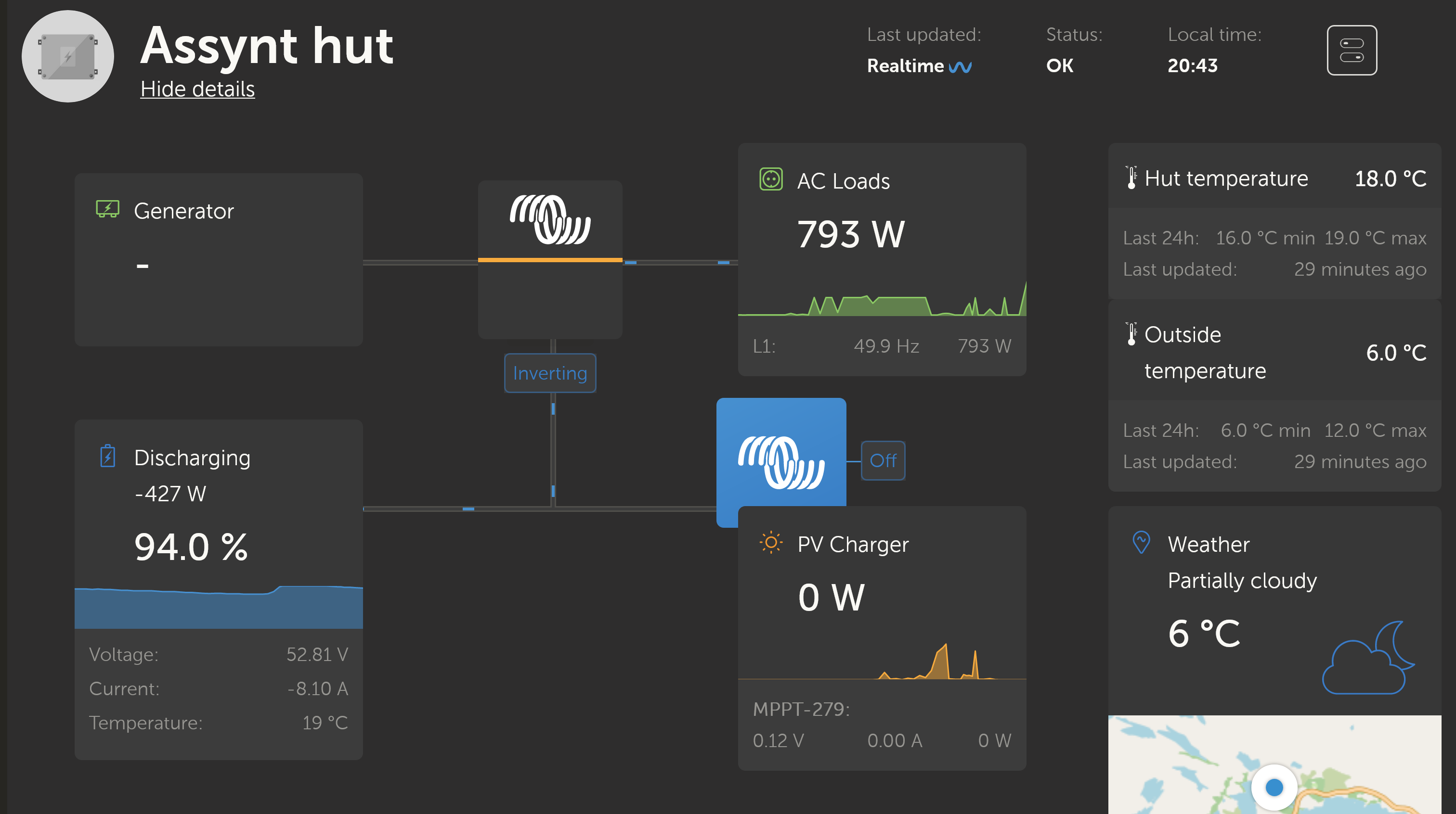
The vrm dashboard display of V, I and W for the PV Charger and the Battery show a power value for the charging battery roughly 40% to 45% of the PV charging power (allowing for a base load of 16W). This is considerably lower than I had expected. This observation is true over all typical charging conditions in the north of Scotland, with the slightly higher efficiency observed with higher PV Charger power. Can anyone confirm if this is normal or suggest what to change.

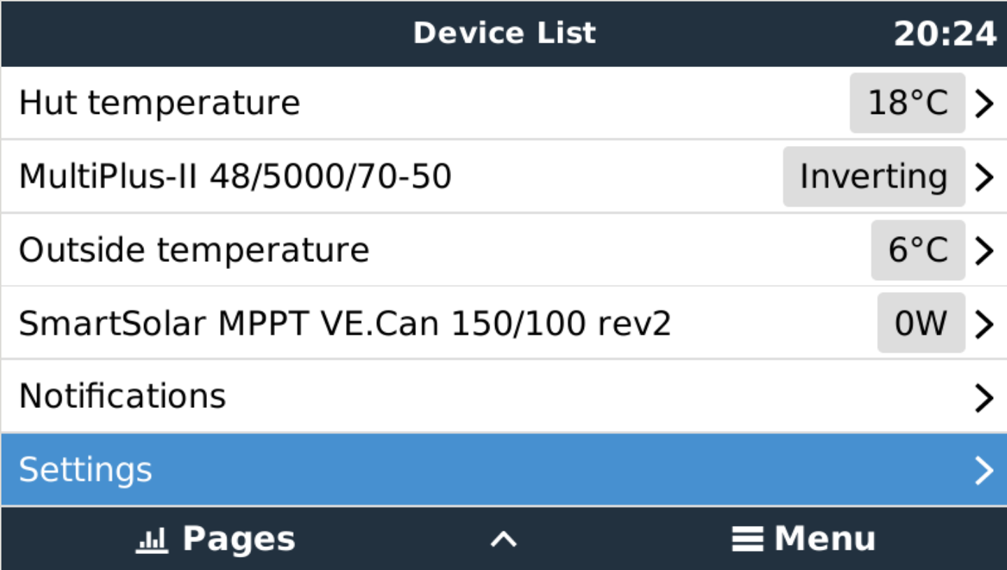
The set up has 4kW PV array, Multiplus II 48/5000/70-50, MPPT150/100-MC4, 2x4.8kW LiFeP04 batteries, CerboGX, GX Touch.

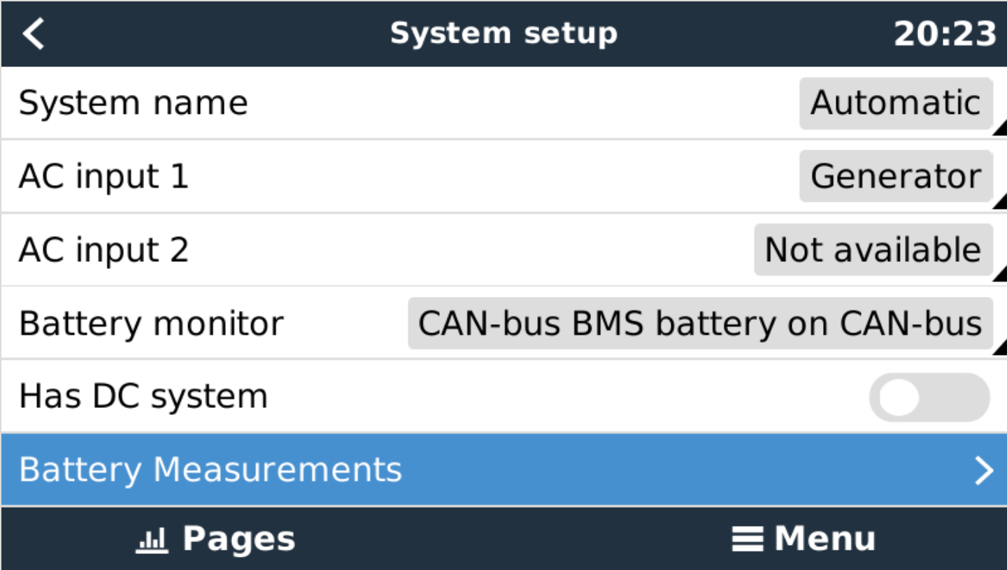
Charge efficiency in VEConfig is set at 95%.

Thanks in advance for any advice.

MPPT Controllers
2 |3000

Up to 8 attachments (including images) can be used with a maximum of 190.8 MiB each and 286.6 MiB total.

5 Answers
kevgermany avatar image
kevgermany answered ·

Panel wattage is measured under specific lighting conditions and temperature. I'm nowhere near as far north as you, currently (pun intended) seeing about 5-10% of panel value. Have maxed out about 80%.

Battery charge efficiency setting is only to aid state of charge calcs as far as I know.

3 comments
2 |3000

Up to 8 attachments (including images) can be used with a maximum of 190.8 MiB each and 286.6 MiB total.

assyntdavid avatar image assyntdavid commented ·

Thanks Kev for your reply, much appreciated. I realise the panel wattage will be well below its nominal max value due to angle incidence, etc, etc. In fact they are performing surprising well when the sun does shine. The discrepancy is between what the mppt controler claims it is putting out and what the battery data says they are receiving. I have come up with a possible explanation, but need to hear back from the installers to check out whether it is plausible. If I am correct I shall report back.

David

0 Likes 0 ·
Matthias Lange - DE avatar image Matthias Lange - DE ♦ assyntdavid commented ·

The battery monitor shows what is going into the battery.

If you have loads running a part of the PV power is going directly to the loads.

Your Multi also needs some power to make 230V even if you don't have any AC loads running.

0 Likes 0 ·
assyntdavid avatar image assyntdavid Matthias Lange - DE ♦ commented ·
Thanks Matthias. I have been allowing for the load which is currnetly ~16W. The current thinking is that the Battery power figure is half what it should be because one of the two batteries has not been connected into the communication bus correctly and its charging current is not been recorded. (Current value to batteries from MPPT is in line with what would be expected from the PV input.) This is a remote mountain site so it will be some days before I have a chance to change anything and check.

Thanks for the suggestions.

David


0 Likes 0 ·
assyntdavid avatar image
assyntdavid answered ·

I apologise for this delayed update re the above. This is a remote location and midwinter festivities and lots of poor weather have meant that we did not return to site until a few days ago. Further investigations on site have confirmed that both batteries are working fine. The issue seems to be that each of the two batteries is 'read' alternately and displayed. Thus the display is only showing the SOC and charge/discharge power of one battery at a time, and if the SOC of each is slightly different as on this trip the display flips from 82% to 83%. (I was able to confirm this be disconnecting a battery from the VE.CAN.) This makes sense but is disappointing, I had assumed the display would indicate the total battery bank charge/discharge power.

The batteries are TN type TN-LFP48100(16S) and are working well apart from the above. When using multiple modular batteries I can see an advantage to being able to check a single module, but seing the total would also be good. If anyone could feedback what happens with BYD or Freedom Lite batteries that would be interesting. Meanwhile I hope this update may be useful to someone else in a similar position.

David

1 comment
2 |3000

Up to 8 attachments (including images) can be used with a maximum of 190.8 MiB each and 286.6 MiB total.

murrayman avatar image murrayman commented ·
@assyntdavid Did you ever solve this? I have 5 of the exact same batteries and I’m experiencing the same thing, Cerbo Gx only displays 1 battery, regardless of what addresses I give the batteries? Any help would be greatly appreciated

Thanks

0 Likes 0 ·
murrayman avatar image
murrayman answered ·

Ignore that I seem to have resolved it,

ID 1 doesn’t work

I put ID 6 as master batt with can plugged into that

And then worked down

ID 5 -slave

ID 4 - Slave

ID 3 - Slave

ID 2 - Slave


No idea why that worked but seems to for me

2 |3000

Up to 8 attachments (including images) can be used with a maximum of 190.8 MiB each and 286.6 MiB total.

assyntdavid avatar image
assyntdavid answered ·

Thank you @murrayman (I hope that's the correct way to direct a reply to you, not done that before). I am exicted that you may have found a way for all batteries to be registered as a 'bank' of batteries and visible. Could I ask you to clarify what you did. I am not sure what you mean by ID 6 (to 1). If this refers to the DIP switches could you indicate how you set them please.

It seems to be good form to include images to support comments. I am including a screenshot from the vrm screen. I turned on the heaters momentarily to show the discepancy in AC load power and battery power.screenshot-2022-10-14-at-20-43-31-assynt-hut-vrm-p.png

I have also included a screenshot of the 'Device List', note that the battery does not appear here.screenshot-2022-10-14-at-20-23-59-assynt-hut-vrm-p.png

The batteries are visible to the Cerbo and do appear on 'System setup' under Battery monitor.screenshot-2022-10-14-at-20-23-04-assynt-hut-vrm-p.png

Thanks again for getting in touch and hoping you may be willing to help further. I cannot visit the hut until the end of next week, so cannot try out any changes on site and report back until then.


2 |3000

Up to 8 attachments (including images) can be used with a maximum of 190.8 MiB each and 286.6 MiB total.

murrayman avatar image
murrayman answered ·

@assyntdavid, not a problem, it was a problem that had been winding me up for some time but finally had a chance to play around with it. I was fiddling with the Dip switches looking at the Can-bus battery details screen on GX and it was initially showing 1 battery online and then as i played around with the dip switches more and more started to come online until i decided to try reverse numbering the battery IDs which seemed to solve my issue.

I see the difference you are discussing, my system has a shunt in it also so i'm not sure if mine is reading correct battery draw because of that?

Re the battery addresses, i have attached the battery user manual which describes the dip switches Id numbers so try referring to them, in order to get mine to work and register all 5 batteries i ordered the batteries as follows:


"Master" Battery (the one with canbus cable) was set at ID 6
"Slave" battery underneath that (linked to above with batt com cable) was set at ID 5
"Slave" battery underneath that (linked to above with batt com cable) was set at ID 4
"Slave" battery underneath that (linked to above with batt com cable) was set at ID 3
"Slave" battery underneath that (linked to above with batt com cable) was set at ID 2

I Hope this helps, Not sure if it was just a fluke or there was method in the madness, i had tried contacting TN with no luck. If you still cant get it reading correctly i recommend fitting a shunt in addition as that is what i have been using for the last 4 months until i had a chance to fully finish off the system and it had been working flawlessly without the battery can-bus fitted at all.

ThanksESS Battery User Manual V4.0.pdf

Scott


2 |3000

Up to 8 attachments (including images) can be used with a maximum of 190.8 MiB each and 286.6 MiB total.