question

lsgv avatar image
lsgv asked

Best architecture for connecting 2 Multiplus II based off-grid systems in series

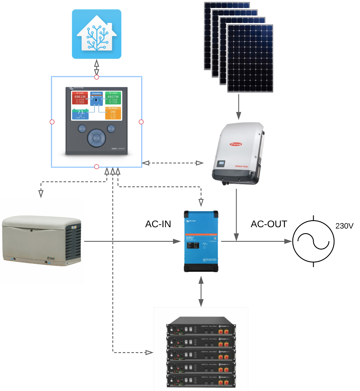
I have an off-grid 15KVA installation that is working flawlessly for more than 2 years and am now going to do a [planned] upgrade. Below a simplified schematic of the set-up: 40x405W panels in 4 strings of 10 connected to 2 Fronius 8kW grid-inverters, followed by 3 parallel Multiplus II 5000, 42kWh Pylontech battery bank and a backup Kohler generator. The whole thing controlled by a CCGX and Home Assistant. This system is installed in the main house.

1665336664518.png


This set-up works well but I had prepared the option to upgrade it if with 2 year's worth real experience I noticed I'd call too often on the generator or for any other reason. I've now decided to do the upgrade and whereas I have a clear target architecture in mind I'd like to turn to this forum for any issues I may have overlooked, improvement opportunities, or any other inputs.

The upgrade or extension is going to be a second Multiplus II based system located in the carport. The basic concept is that the new system will replace the generator at AC-IN of the existing system, and will have the generator connected at its AC-IN in turn. Below a simplified diagram of the target solution.

1665339369714.png


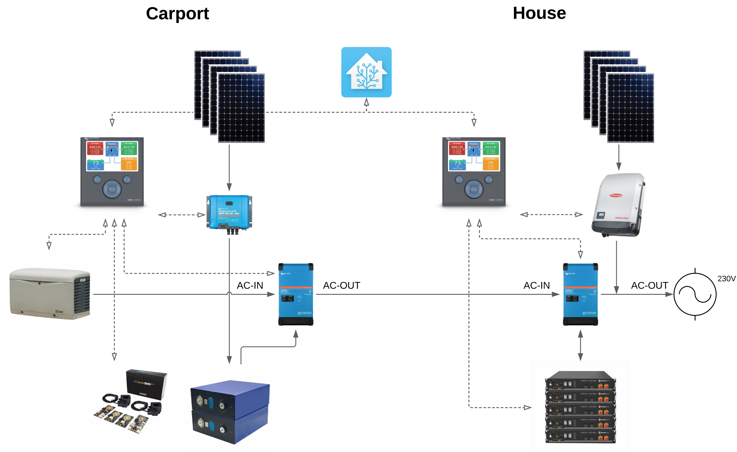
Both systems are connected by 50mm2 cable which at 50A will give me less than 1% voltage drop at 230V, acceptable.

Because I already have the proven and trustworthy existing system I plan on going more DYI with the new one and go for EVE prismatic cells with 123BMS which is one of the 2 BMSes known to work well with Victron. On the charge controller and inverter I want to stick to Victron because of compatibility, easy of use, quality, you name it.

I will have 2 Multiplus II pushing out a maximum of 10KVA but above all, capable of accepting up to 8kW from the generator as their maximum CC charge current is 70A each. The panels will be connected to MMPTs so I solve the potential blackout issue with the current AC-connected only set-up. The whole managed by a second CCGX or Cerbo and HA on top.

The existing House set-up with 15KVA output is enough for all the loads so I don't need the new Multipluses to assist or increase grid capacity.

The control idea for this set-up is the following:

- Configure the new system as a generator in the house CCGX and use the generator start/stop assistant to turn it on/off exactly as I do today, based on SOC. AC-IN current limit would be 42A as I have today keeping the power transfer under 10KVA.

- Connect and configure the generator to the new system and use the generator start/stop assistant to turn it on/off based on SOC. Current limit also 42A to respect the sum of the Multipluses CC maximum charging current of 70A each.

This configuration has the advantage of creating 2 totally independent systems which greatly increases the resiliency of my off-grid installation.

I cannot easily merge the 2 battery banks into a single one because of the logistics and distance between house and carport. I thought about it as an option but it would require moving the existing House Multipluses and batteries to the carport which I don't want to do because "if it ain't broke, don't fix it". It would only save me the cost of the 2 new Multipluses which would be more than negatively offset but the extra cost of the Pylontech batteries I would have to use, instead of the EVE, to extend the now single bank.

Questions:

- Are there any major issues I'm overlooking?

- Is there a better architecture considering the situation?

- Is there a better control logic?

Thanks in advance for any comments, remarks or pointers.

Multiplus-IIoffgrid
1665339369714.png (1.1 MiB)
1665336664518.png (566.9 KiB)
1 comment
2 |3000

Up to 8 attachments (including images) can be used with a maximum of 190.8 MiB each and 286.6 MiB total.

Alistair Warburton avatar image Alistair Warburton commented ·

I have a Multiplus 48/5000 feeding a Multiplus 24/5000 as you describe and don't have any significant issues with the setup. Genny > 48 > 24 > Distribution. PV Charges the 48 (DC)

Note they are the original versions not the newer Multiplus-II

I have enabled Large OS with Node Red on a Cerbo which directly controls the 24 and monitors/control the 48, which has a CCGX, using Modbus registers.

The only time I have to do anything odd is when I start the generator. The setup can be a bit unstable when the generator first connects, rapidly changing the generator load which then causes it to disconnect again. I have controls that put the 48 into charge only whilst the generator stabilises and then enables output so that the 48 can feed the 24 again.
Once they are both connected and the genny is warm it works just fine. In fact it will reconnect without fiddling about should it need to. (This is defiantly a generator issue)

The lowest AC input limit you can set is 4A so you cant use that to split the charge.

My strategy was to enable DVCC on the 24 because that gives me control of the DC charging current and thus a way to determine how much current each battery is getting.

The AC limit on the 48 fixes the generator load while the DC limit, via DVCC, on the 24 determines how much of the available input is used to charge the 24 with the balance either going to loads or into the 48. I use the AC input limit, dynamically, on the 24 to load share when I need more than a couple of kW.

I would get slated for not saying this, so I am going to...
This strategy is not a supported configuration and although I have done it I am not an expert and in no position to recommend anything. It works for me and offers redundancy and flexibility, which is why I did it.

BTW How are you connecting HA, I am just about to do that and was going to use Node Red, how have you done it?

0 Likes 0 ·
4 Answers
lsgv avatar image
lsgv answered ·

Thanks for your feedback. HA connection and a couple of questions below.

1. Connecting GX devices to HA: 2 main options, MQTT (plus Node-Red if you want) and modbusTCP. I started out with MQTT but have since changed to modbusTCP and prefer it. Call me old-school but I prefer to be as close to the machine as possible and MQTT adds a broker on the GX and another on HA. Both work well so up to you. I wrote a post on that here

2. If I understand well PV is only on the upstream 48 so what is the purpose of the downstream 24? Are they supplying 2 different grids/loads in different locations? I also understand both have their own battery banks?

3. My generator doesn't seem to have stability issues at start-up. Nevertheless, I programmed HA to gradually increase AC-IN max current at start-up and gradually decrease it at shut-down. Especially the shutdown part allows some form of cool-off like what the generator does when exercising. This reduces the oil temperature peak when stopping.

My issue, partly documented here, is to avoid back feeding into the generator when PV power suddenly increases a.o. when partly cloudy sky. I solved this by limiting the cut-off SOC at 80% (generator stops when SOC => 80%) as I empirically noticed that is when the battery charge current sort of starts to drop and hence the system would be more susceptible to PV power fluctuations not being instantly absorbed by the batteries), AND by programming HA to stop the generator if PV production stays above 5kW for some minutes (5kW arbitrarily chosen but reasoning is also not to run the generator when there is enough PV available).

2 |3000

Up to 8 attachments (including images) can be used with a maximum of 190.8 MiB each and 286.6 MiB total.

lsgv avatar image
lsgv answered ·

About the disclaimer that this is not a supported configuration. Maybe I'm wrong and that's why I reached out to this forum, but when I thought about this I just couldn't think of why this wouldn't work. Both systems are totally independent in their components including the battery banks and the controls. For the upstream Carport system, the downstream House is nothing more than a regular load, there is no way it can detect that it is another PV/inverter/battery system. And for the downstream House the upstream Carport is nothing more than a grid and there is also no way it can detect it is another PV/inverter/battery system. So this architecture does work and my question has more to do with "what is the preferred configuration" and "are there any issues I'm overlooking"?

The back feeding issue discussed above is one. I have the potential back feeding from Carport to generator resolved as explained above. But what about the potential back feeding from House to Carport? Is that really an issue or since House is connected at AC-OUT of Carport is it not comparable to a PV inverter? Assume there is energy backflow from House to Carport, isn't the Carport Multi+ going to use it to charge its batteries? But what if they are already fully charged? Isn't the answer to configure downstream House as ESS now that it is not off-grid anymore as connected to a [permanent] grid at AC-IN? ESS allows to configure zero back feeding with Fronius PV inverters. And allows more optimised strategies such as "keep my batteries charged at 80%" etc. By going ESS on the upstream House and DVCC on the downstream Carport I'm thinking is a better option than DVCC on both and managing their interconnection on/off with the generator switch.

What do you think?

2 |3000

Up to 8 attachments (including images) can be used with a maximum of 190.8 MiB each and 286.6 MiB total.

Alistair Warburton avatar image
Alistair Warburton answered ·

"If I understand well PV is only on the upstream 48 so what is the purpose of the downstream 24"

Same loads ,the 24 system is there to...

1. Add capacity and redundency. It may get its own solar charger too at some point.

2. Allow me to try budget batteries, I am currently using 6 Ultramax 100AH 12 units. 3 strings 300Ah in total. which seem to be working well.

My 48V system uses a BYD pack which is great but not possible to add to incrementally. Installing another paralell 48 would have been the recomended solution but wouldnt have offered the flexibility I have now.

1 comment
2 |3000

Up to 8 attachments (including images) can be used with a maximum of 190.8 MiB each and 286.6 MiB total.

lsgv avatar image lsgv commented ·
Thanks, I get it, good move.
0 Likes 0 ·
lsgv avatar image
lsgv answered ·

I see we're chatting on another thread too :). As I understand your two systems have their own set of batteries so your config is basically the same as I'm envisaging. What settings do you have for the systems? Both DVCC or anything different? Have you thought about the ESS/DVCC mix I discussed?

You also mentioned you have "decided to disallow any form of back feed on either inverter so simply dont have to deal with it". How did you do it?

2 |3000

Up to 8 attachments (including images) can be used with a maximum of 190.8 MiB each and 286.6 MiB total.