question

marv21 avatar image
marv21 asked

ESS / Victron ignoring BMS Parameters Overcurrent / Not feeding in all

Hello,

as Iam new but did all the Trainingslessions, iam not 100% sure if i did everything correctly.

Iam currently just using one Battery (yes more to come, for 1:1 Rule and Offgrid situations).

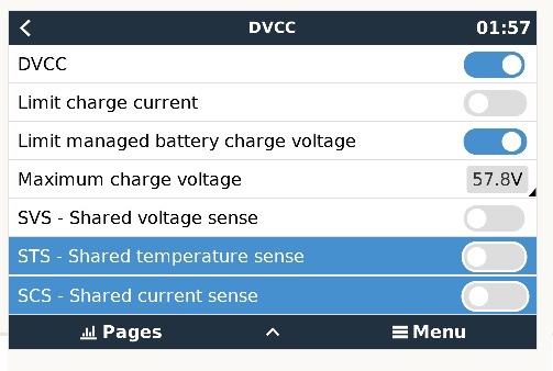
The Battery is connected via CAN-BMS and the Parameters are shown correctly in the Console:

parameters.jpg


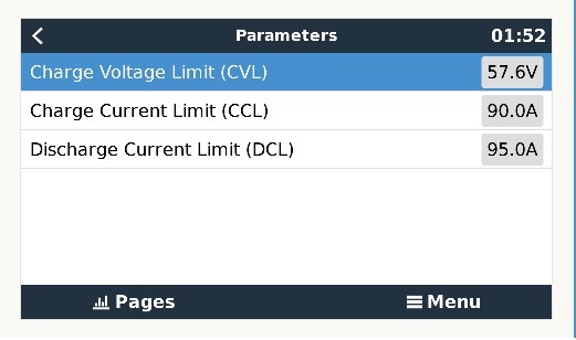
As you can see, CCL and DCL are around 90A.


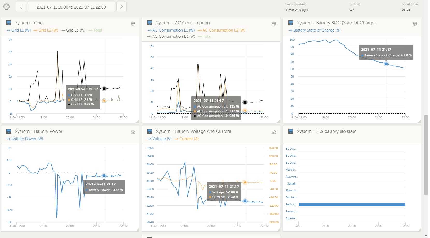
But, if I start a big Load, ESS tries to discharge with over 190A, sending my Battery in Overcurrent Alarm (Battery BMS is shutting down).

overcurrent.jpg

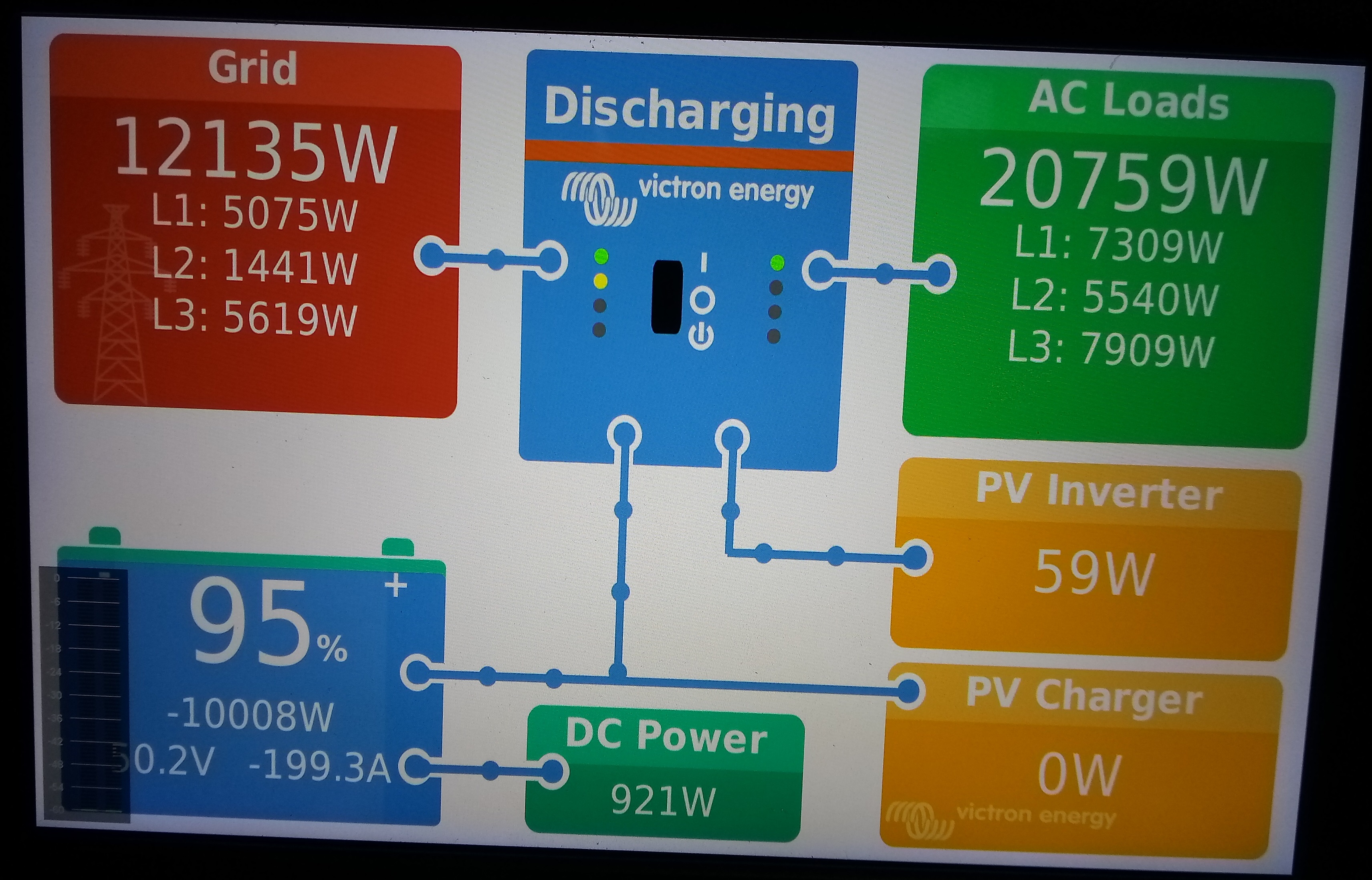
The other way around, if there is a decent load (2000Watt), the Battery is only discharged with around 1000W (20A) - letting me pay for 1000W from the Grid...

Also the Battery is max Charge with 20A, even there is more PV Power (feeding into the Grid 4000W)


I dont know whats wrong, could someone check my setting please:systemsetup.jpgess.jpgdvcc1.jpg
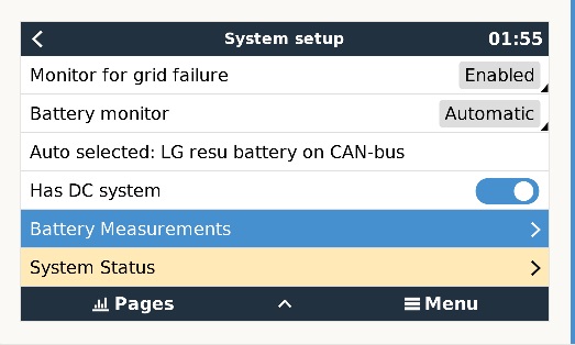
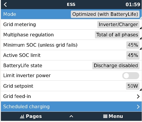
Console-Pictures are taken in the Moment the SOC Limit was reached. But the Bug/missconfiguration that iam encountering is with Full Battery, 75% SOC and so on.

Multiplus-IIcerbo gxESS
systemsetup.jpg (46.2 KiB)
dvcc1.jpg (49.6 KiB)
overcurrent.jpg (1.6 MiB)
parameters.jpg (32.9 KiB)
ess.jpg (62.1 KiB)
ess.jpg (62.1 KiB)
2 |3000

Up to 8 attachments (including images) can be used with a maximum of 190.8 MiB each and 286.6 MiB total.

1 Answer
Guy Stewart (Victron Community Manager) avatar image
Guy Stewart (Victron Community Manager) answered ·

Hi @Marv21,

Which battery are you trying to use? What does the Victron battery compatibility guide say about your current sizing?

The Victron system runs a load priority, what that means is that it will attempt to power the load that you demand first.

The discharge current limit is not a strict limit that is able to always and immediately be enforced by the system, once the immediate load is provided for, then it will attempt to balance out the demand to match those parameters, but this will happen after the load is provided, so it can result it overload situations.

The remedy is to increase the capacity of the system to provide for the loads that you're trying to run (or reduce the peak loads).

If that isn't possible, another remedy is to place the large loads on the AC-input side of the inverter - that way the grid provides those loads first, and then the Victron system will attempt to fill in for them over time, so the balancing delay is working in your favour (instead of against it).

The downside of that approach is those loads will not be able to run during a blackout, but it sounds like they wouldn't be able to run anyway given the system sizing.

3 comments
2 |3000

Up to 8 attachments (including images) can be used with a maximum of 190.8 MiB each and 286.6 MiB total.

marv21 avatar image marv21 commented ·

Thanks for your answer.

Its not easy to rewiring the high loads to another Input.

Right in the Moment my sizing is way to small. I dont get why the Victrons starts with "giving all in" and then trys to reach die Overcurrent Setting and not start small and then ramps up slowly to reach the Overcurrent Setting... (In On-Grid ofc.)


But even with this, i dont get why the Battery isnt charging more then 20A (Grid Set 50W and Grid is -2000W)


And why it dont Balance my Importing to 50W (no Inverter is fully use - i know Victron dont support symmetrical ESS feed in)


vrm-nichtausgleichend.jpg


0 Likes 0 ·

This might be wrong, as I am not an engineer;

Most of the time for most systems the 'limits' as communicated by the system ARE soft limits in that they can be exceeded for a short period of time. This essential in off grid situations, as for some loads such as start up of induction motor loads are MUCH higher (8X!) than their continuous load.

At a low level, you need to understand a bit more about how the loads are electrically provided for.

There is a battery voltage, and a transformer, and FET bridge. That provides the AC waveform (i.e ~230V at 50hz) on the inverter side.

Then there is the grid voltage (~220-240V at 50hz).

If there is a differential voltage in the circuit, Current (A) will flow from the higher voltage to the lower voltage. The Multi uses this effect by raising or lowering the synchronised AC voltage that it provides. If the Multi voltage is higher than the grid voltage, current will flow from the battery (through the inverter) out to the AC side of the system. If there is a load on that side, current will flow to the load.

When a bigger load turns on, it adds resistance to the circuit, this reduces the voltage. The multi is providing a higher voltage, so in that moment MORE current will flow from the Multi to the load than from the grid (which is providing a slightly lower voltage).

The system will monitor those different voltages (the grid voltage, the multi voltage) and the current flow, and then adjust the Multi output voltage accordingly to keep within the limits.

But all that happens after the fact of the load turning on, the circuit voltage dropping and the multi maintaining that target voltage supplying the current required to do so (until an overload).

Note this isn't an overload of the Multi, but an overload of your battery BMS. The Multi will in most cases able to withstand the temporary overload and the time it takes to reduce its voltage to below that overload threshold so that the difference in current required can be provided by the grid.

Some batteries BMS handle that overcurrent situation better than others, and that must be a critical part of matching a battery with a load type in a system design.

0 Likes 0 ·
marv21 avatar image marv21 Guy Stewart (Victron Community Manager) ♦♦ commented ·

Thank you for your detailed answer. I understand know. The BMS of the Battery is indeed the one that shuts down after 10secs or more at 200A. I think i will just add one or two more Batterys to avoid this, but neiterless if i see the Remote Console the Multi is very slow regulate to a lower Current.

0 Likes 0 ·