Right now changing 1980 Morgan 462 from Ferro resonant charger and converter with flooded batteries where the positive leads routed through a " 1-2-both-off " switch and each battery had Negative cables going to a bulkheaded mounted Buss bar of sorts. With 1-2-B-O switch supplying power to a similar bus bar on bulkhead for loads to attach to...
So trying to figure out where to add the smart shunt...How the multi should hook up to the DC side of the house as all I see is DC cables going to and from batteries and one trickle charger line out. I am using the 2 250A 8D as the house that is with both attached to the selector switch and to the ground. But see now Negative or positive out other than trickle charger so how do I get from the multi to the bus bar and track usage.... I do not have a 712 as pictured here, am planning for a CCGX as soon as I see if I have to add any other items between the Multi and the CCGX to be able to control and view the system.
So take a look at the pic and Help a brother out....I have no ego when it comes to electrical so feel free to laugh..LOL
But help also Please!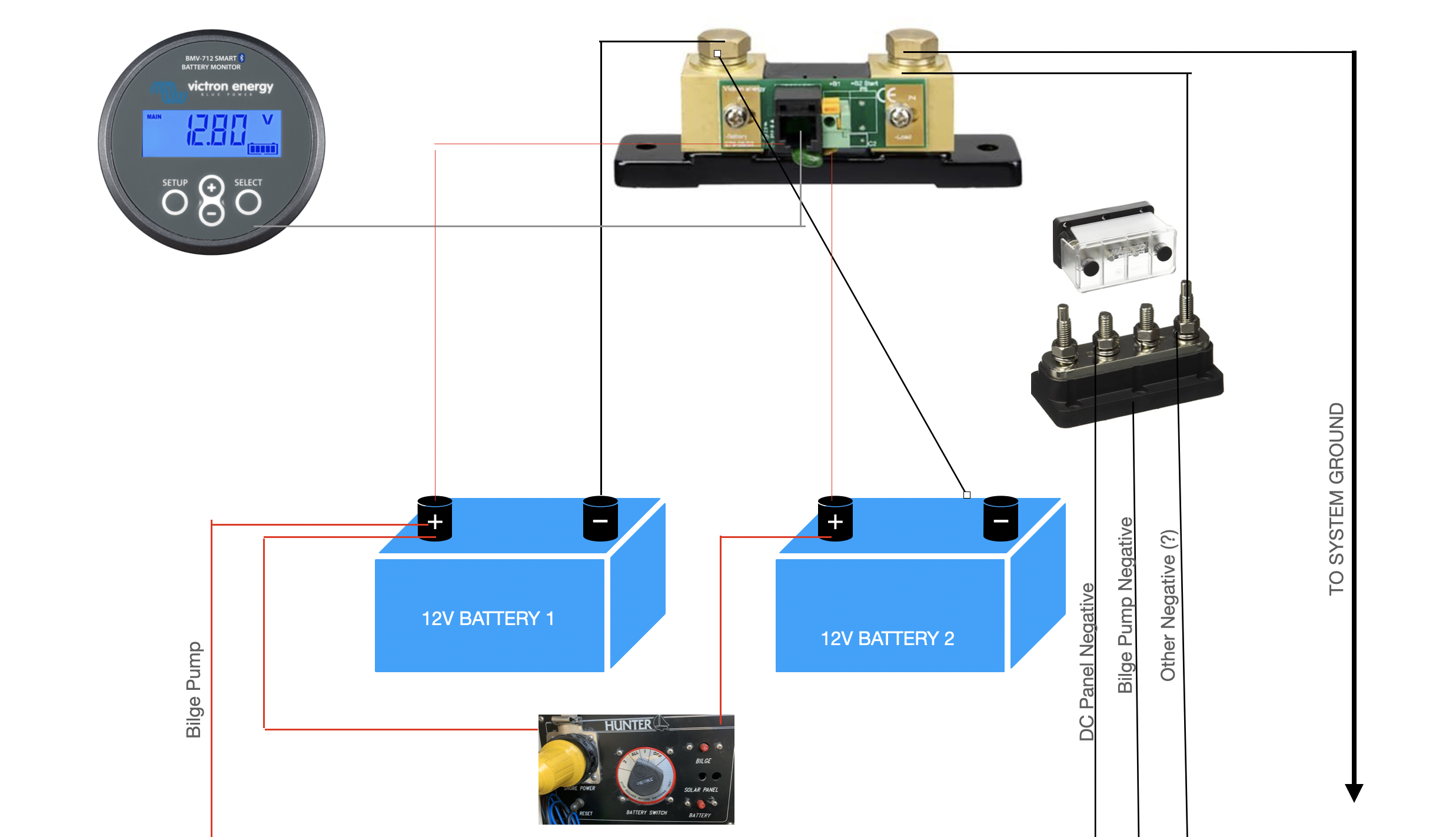
asked
Best way to hook up shunt and Victron Multi plus 3000w 12V 120A batteries are 2 identical 250A 8D
Assuming that Battery 1 is your house bank, and battery 2 is a starter battery, rather than a 2nd house bank:
You have a common negative bus bar. (True Ground)
Battery 2 connects negative terminal directly to the bus bar, positive is monitored by the aux input on the smart shunt.
Battery 1 negative connects to the bus bar via the smart shunt. NO OTHER connection is made to this battery negative - all negatives go to the bus bar.
Smart shunt temp and power sensor connects to positive of battery 1.
Battery charging depends on how frequently the vessel is used, and whether she has access to shore power. The 1-2-B-0 switch should be used to control power to the engine starter. Under no circumstance should this be left in the B position for any long period of time, as this will allow the house loads to drain the engine battery. House bank should have an isolator switch (1-0) to the house load positive bus.
Battery protection switches would also be a good idea, particularly on the house bank, but make sure that lighting circuits (DC - LED) bypass this protection.
Mike thanks for the input.....I am just getting to this stage of learning what I actually have so please excuse the dumb questions...but If I don't keep the selector switch to both while at dock plugged in or while the engine is running, I just don't; see how each battery no matter what I designate them ....and the charge wires go from the charger (being replaced by a multiple a whole other set of questions) to a positive bus bar then on to the selector switch ..how would either battery get charged if selector is on other battery and not on both? As I have just two cables from each battery going from + & - of each battery to a + & - bussbar...no additional cables to facilitate charging....with the 1-2-B-O switch the only thing between bus bars and batteries so no additional charge wires....
I am going to do like every other guy that doesn't know stuff or why it was set up like this and just blame the Previous Owner....LOL
Thanks for the input and I will try to limit the what-if questions as the more I learn the more I think I am going to have to rewire the whole section pertaining to START, HOUSE, CHARGE, SHORE POWER, AND GEN SET part of the boat's system.
Again thanks for the input...