question

northernboy avatar image
northernboy asked

Grid and new Generator have different Phase Sequence, how to correct?

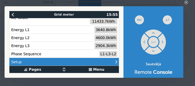
My 3 Phase Grid sequence is (According to the grid meter on the color controller) L1-L3-L2

screenshot-2021-06-09-at-155434.png


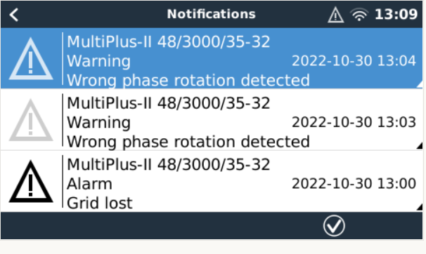
I just connected my new generator and with the....


Multiplus's switched to "on" Inverter lights on constant. No Battery Charging.

Multiplus's switched to "charger only" main lights flash on line 1,2, main and float lights flash on line 3, No Battery Charging.


I then checked my 3 phase Generator sequence and (According to the grid meter on the color controller) it's L1-L2-L3


What is the best way to fix this issue, I guess the system is set up for L1-L3-L2 as it all works fine when the grid is connected.

Generator
2 comments
2 |3000

Up to 8 attachments (including images) can be used with a maximum of 190.8 MiB each and 286.6 MiB total.

harold avatar image harold commented ·

Just can switch 2 connections of the generator, i suppose???

0 Likes 0 ·
northernboy avatar image northernboy harold commented ·

I did wonder if I could just switch L2 and L3 on the Genset plug wiring but thought I would ask first.

0 Likes 0 ·
2 Answers
northernboy avatar image
northernboy answered ·

I am answering my own question in case someone has the same issue. I switched L2 and L3 over on Genset, now Genset and Grid have same phase sequence. Everything now works OK.

2 |3000

Up to 8 attachments (including images) can be used with a maximum of 190.8 MiB each and 286.6 MiB total.

ted avatar image
ted answered ·

I have the same problem. So you did only switch the L2 and L3 at the IN and OUT Port from the EM24, or?

12 comments
2 |3000

Up to 8 attachments (including images) can be used with a maximum of 190.8 MiB each and 286.6 MiB total.

wkirby avatar image wkirby ♦♦ commented ·

As he says above, he switched L2 and L3 on the generator.

0 Likes 0 ·
marekp avatar image marekp commented ·
@Ted

Switch L2 & L3 only at the EM24 input.

0 Likes 0 ·
ted avatar image ted marekp commented ·

I have a 3 phase Multiplus System. Think, if I only change the EM24 Input Port, then a phase rotation error would appear in the MP System, since you set each Multiplus to a specific phase in the VE Configurator

0 Likes 0 ·
marekp avatar image marekp ted commented ·
@Ted

The error you see is caused by the difference in phase rotation between incoming AC and your Multiplus system.

You have 2 options.

1. change phase rotation on the input of your system (EM24).

2. change phase rotation of your Multiplus system.

First option is simpler and does not require changing phase rotation on all your 3 phase loads.

0 Likes 0 ·
ted avatar image ted marekp commented ·

"The error you see is caused by the difference in phase rotation between incoming AC and your Multiplus system. "


To clarify. The L1-L3-L2 Phase sequence in the Cerbo EM24 overview currently throws NO phase rotation Exception in the MP system at all. With an additional 3-phase generator at the AC-In, it is another thing.

I can of course change L3-L2 already at the output of the main switch for the AC-IN of the MP System. But still not sure, that I then need not reconfigure the MP-2 and MP-3 with the configurator since they get another phase. But the MP has each a phase detection, like the EM24. So, is it possible that the EM24 "rewires" the L3-L2 already?

0 Likes 0 ·
marekp avatar image marekp ted commented ·
@Ted

Change the EM24 input AC phase rotation and see what happens. :)

0 Likes 0 ·
ted avatar image ted marekp commented ·

I did test it. Turned off the AC-IN main Switch, while the MP System switched to battery-only mode. Then rewired L3-L2 and turned on the AC-IN main Switch. Not even a relais test started ...

Result:

1667131898433.png


After i did unchange it, the relais test worked fine.

0 Likes 0 ·
1667131898433.png (87.4 KiB)
marekp avatar image marekp ted commented ·
@Ted

Can you try to change L2 & L3 on the output of the EM24?

0 Likes 0 ·
ted avatar image ted marekp commented ·

Without any further connection to the MPs, you see already in the EM24 Menu the phase order of the 3 Phases, so L1-L3-L2 are at the EM24 Display. So to "fix" this, I think it is needed to rewire L3-L2 at the EM24 input Port and then reconfigure the L3 and L2 Multiplus via the ve configurator

0 Likes 0 ·
marekp avatar image marekp ted commented ·

@Ted

Changing phase rotation at the input of EM24 and at the MP-II will not fix it.

Change needs to be done only in one place.

Before you do the reconfiguration of MP-II, change L2 and L3 at the EM24 output.

I had 2 systems with this L1-L3-L2 in the grid meter menu.

One would not connect to grid with the "Wrong phase rotation detected" massage. Change L2 and L3 on the EM24 AC input fixed the problem.

Second one worked but system had problem with balancing phases. Change L2 and L3 on the AC out of EM24 fixed it.

0 Likes 0 ·
ted avatar image ted marekp commented ·

Switch L3/L2 at input and output (EM24) should work. The 3 fields remains, but the "measuring channel" is exchanged only. Will test it and tell you

0 Likes 0 ·
ted avatar image ted marekp commented ·
I changed today IN and Out Port at the EM24 to switch L1-L3-L2 to L1-L2-L3. Worked fine without error.
0 Likes 0 ·