question

mtnscott avatar image
mtnscott asked

MultiPlus Ground Relay Question

I have a multiplus 12/3000/120. The manual states on page 9

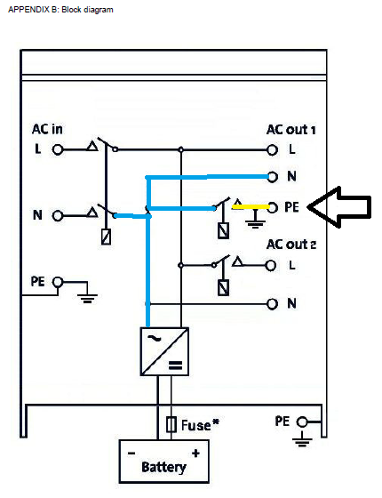
"The MultiPlus is provided with a ground relay (relay H, see appendix B) that automatically connects the Neutral output to the chassis if no external AC supply is available."

If you examine the appendix B of that same manual it shows a relay action on "PE" of AC Out, L of AC Out 2, and the input L,N. It does not represent what is stated on page 9 where the AC Out N is connected to the chassis. Can you please clarify?

MultiPlus Quattro Inverter ChargerGrounding
2 |3000

Up to 8 attachments (including images) can be used with a maximum of 190.8 MiB each and 286.6 MiB total.

3 Answers
Kevin Windrem avatar image
Kevin Windrem answered ·

Safety ground (aka PE) must be bonded to Neutral once in the electrical system. This is generally at the service entrance. The purpose of this connection is to divert any fault current safely to the electrical return and trip the associated breaker. Otherwise, hazardous voltages may appear on equipment chassis.

When the Multi is inverter mode, the shore power connection (line and neutral) are disconnected, so there is no fault current path through the service entrance. When the AC input relay opens, the internal ground relay closes providing a neutral-safety ground connection. All AC output neutrals are connected together inside the Multi (or Quatro), so all AC output neutrals are also connected to safety ground.

Multi/Quatro programming allows the input relay to be disabled in special situations where the safety-neutral connection is made elsewhere. But generally, the ground relay should not be disabled.

3 comments
2 |3000

Up to 8 attachments (including images) can be used with a maximum of 190.8 MiB each and 286.6 MiB total.

sneruh avatar image sneruh commented ·

Just to seek clarification: then when in inverter mode, safety ground connection gets made inside the chassis and then via the ground connection on the outside of the chassis which is connected to ground at the main panel?

0 Likes 0 ·
Alexandra avatar image Alexandra ♦ sneruh commented ·
@Sneruh

Make the usual earth connection to the DB using the AC terminals in the inverter.

Where it connects, whether it is the studs with lugs or the terminal blocks, or bus bar will vary according to the model being installed.

Inverter Chasis grounding is done for other reasons. That being said it is all common.

1 Like 1 ·
jp-in-chicago avatar image jp-in-chicago Alexandra ♦ commented ·
I have a new MultiPlus 2, out of the box and never power/connected. According to Appendix B Block Diagram. Relay H(not labeled) is connecting PE and Neutral. I am measuring an open circuit. Is this proper? page 9 said they should N chassis(PE) should be common? Please clarify. Thank you
0 Likes 0 ·
Alexandra avatar image
Alexandra answered ·

@mtnscott

The Neutral is common inside the Mutli. The relay will connect the PE and N lines. Normally this is done at the DB board, but when disconnected for RCDs to work the bond needs to be remade.

The block diagram is just that a diagram not a physical representation of where the components actually are.

The second relay on the AC2 out L is a programmable relay for connecting or disconnecting loads based on load or SOC or Grid input, or whatever conditions you want. Can be programmed in the assistants tab in Ve Config.


The reference from the page 9 to relay marked H, H is not marked. However the connection is there in appendix B, the ground neutral connection in the block diagram as described for the reasons described above.

1622399506385.png

https://www.victronenergy.com/upload/documents/Manual-MultiPlus-3k-120V-(firmware-xxxx4xx)-EN.pdf diagram taken from this document, Appendix B.


1622399506385.png (89.8 KiB)
2 comments
2 |3000

Up to 8 attachments (including images) can be used with a maximum of 190.8 MiB each and 286.6 MiB total.

mtnscott avatar image mtnscott commented ·

So does the case connection wire gauge need to match the battery wire gauge or the AC wire gauge?

0 Likes 0 ·
Alexandra avatar image Alexandra ♦ mtnscott commented ·

The AC wire gauge.

It is neutral connected, neutral is ac. When you see the unit terminals it will be clear what needs to be done, they are marked.

0 Likes 0 ·
Kevin Windrem avatar image
Kevin Windrem answered ·

The internal relay that connects the output N to PE only closes when the unit is in the inverting mode. With no power to the unit there should be no contenuity between either N and PE.


You will however see low resistance between N and L on the output because the transformer is connected directly to those terminals.

No continuity between any of the input terminals should exist with power off and everything disconnected.

Hope that helps

2 |3000

Up to 8 attachments (including images) can be used with a maximum of 190.8 MiB each and 286.6 MiB total.