question

randy-putnam avatar image
randy-putnam asked

Please take a look at my final install

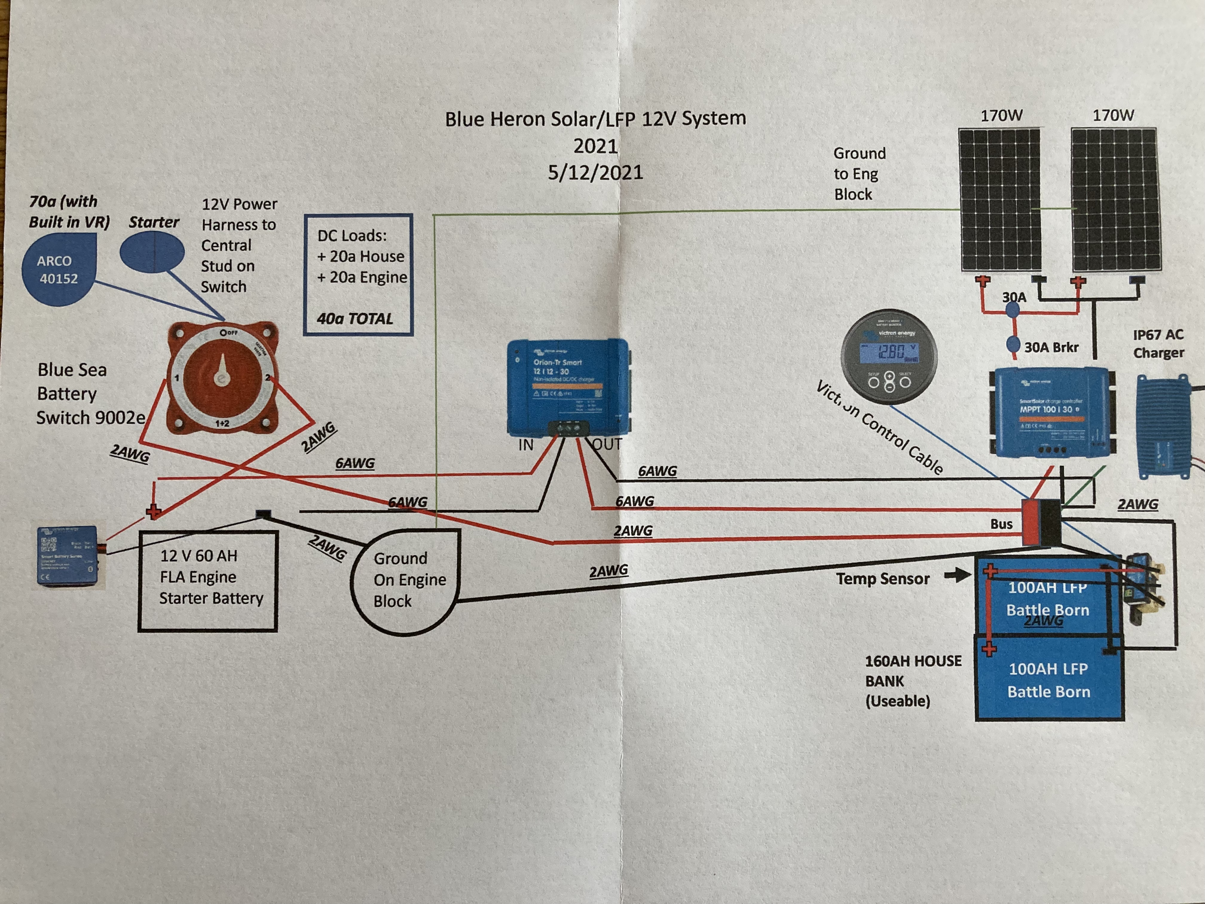
Attached is a schematic of my electrical power system on my 1977 Trojan F26 cruiser. Everything is working fine. BMV712 is networked with the MPPT100/30 and the 2 170W PVs are supplying adequate power to the 200AH LiFePo4 house bank. The original system powered by FLA deep cycle batteries.

Please take a look at the schematic and give me your thoughts. Much appreciated!

fff2571a-431b-47b5-a8ab-05f756423870.jpeg

victron
2 comments
2 |3000

Up to 8 attachments (including images) can be used with a maximum of 190.8 MiB each and 286.6 MiB total.

seb71 avatar image seb71 commented ·

Probably a drawing error: the black wire between the battery negative and negative bus bar should be a red wire between the battery positive and the positive busbar.

And you should have a fuse on this wire (and on all positive wires connected to a battery/busbar).

Even better, wire each battery to the busbar/shunt.

0 Likes 0 ·
randy-putnam avatar image randy-putnam seb71 commented ·

You’re right about the drawing error. The black wire to the battery positive is the neg side of the temp sensor that goes to B2 of the shunt. I did not show it,but all positives are going through properly sized MRBF at the positive side of the bus as well as the positive of the engine battery.

0 Likes 0 ·
1 Answer
Kevin Windrem avatar image
Kevin Windrem answered ·

You have drawn connections from both sides of the shunt to the negative bus bar. Nothing except the shunt should be connected to the battery negative, so the wire from the lower battery negative to the bus bar should be eliminated. Otherwise, the shunt won't properly measure current in and out of the battery and provide bogus SOC numbers.

Switching the battery switch to the 1+2 position shorts out the Orion charger which is probably not a good idea. It might be a better idea to provide switching to reverse the Orion charger input and output connections so the house battery can charge the engine battery in an emergency.

You should take positive off one battery and negative off the other to better balance battery usage. Treat every connection as if it were a resistor and you'll see why.

Fuses to protect wiring from a short circuit that would cause battery current to flow through the short should be installed for every connection leaving the battery.

1 comment
2 |3000

Up to 8 attachments (including images) can be used with a maximum of 190.8 MiB each and 286.6 MiB total.

randy-putnam avatar image randy-putnam commented ·

Thanks. The drawing doesn’t show it, but the battery side of the shunt is only connected to the battery bank neg and the load side of the shunt is connected to the neg of the shunt. I connected the “back” battery neg to the charging neg and the “front” battery pos to the charging pos for better “balancing” of both batteries when they’re being charged.

I agree about the 1+2 switch, but am careful about never using that setting. I’m not sure I want to reverse the in-out of the Orion as the present set up is there to keep the 70A engine alternator charging current to the LFP house bank under control when I’m underway.

I’m using properly sized MRBF fuses at all positives, but don’t show that it in my drawing, which I need to do

Appreciate the feedback!

0 Likes 0 ·

Related Resources

Additional resources still need to be added for this topic