question

alexg avatar image
alexg asked

Wiring Diagram Feedback

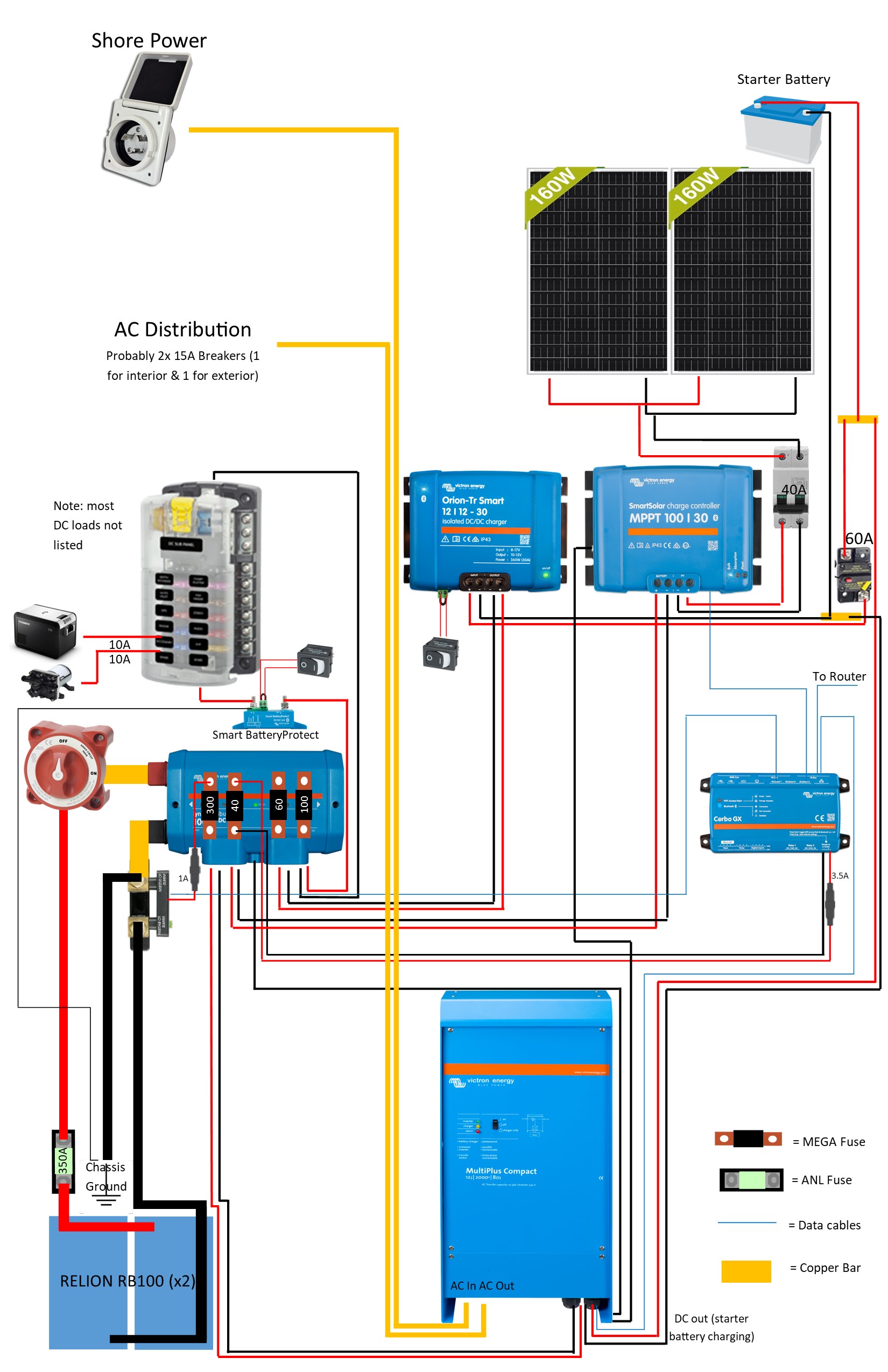
UPDATE 5/11/2021: Please see the updated wiring diagram below with a Multiplus and larger batteries.

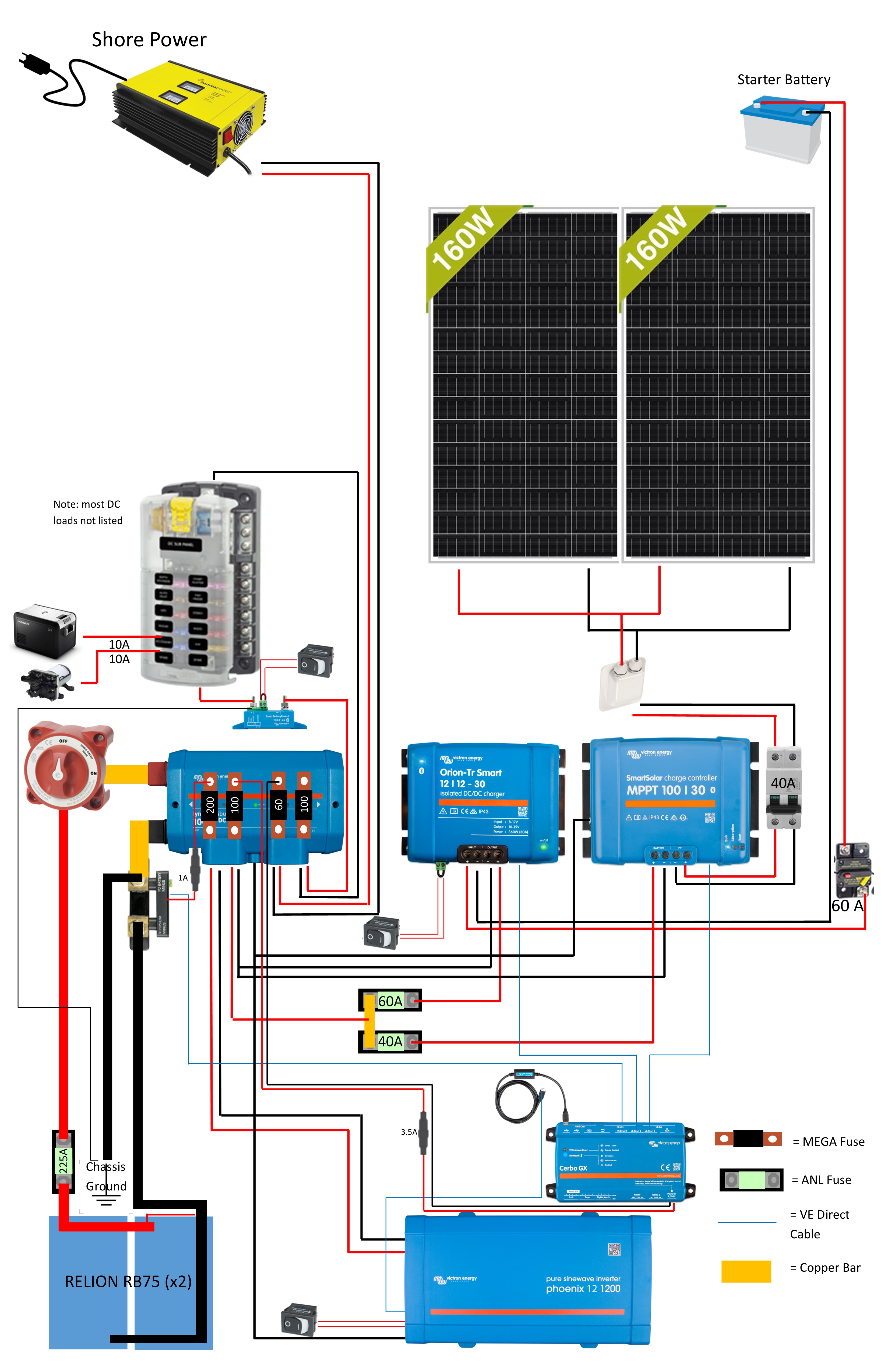
Hi all. I've created a wiring diagram for the electrical system I am going to install in my vehicle. After sending it to a few friends for feedback, I figured it would be a good idea to try and get some feedback from people who may know more about the Victron hardware specifically.

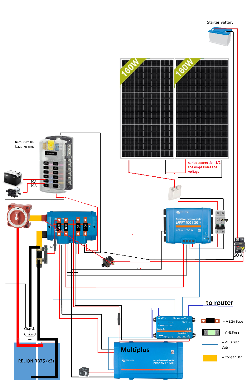
The batteries shown in the diagram are 2x Relion RB75, but I am considering going with RB100's to have more of a buffer.

If it makes any difference, this is going in an SUV (Ford Expedition EL)

One thing I've been trying to find is a different shore charger with a charging profile specifically for lithium (not a Multiplus, too expensive). This Samlex charger only has lead-acid profiles, which the Relion batteries accept but I figured lithium specific is better.

The system is fused for more power than the batteries can deliver (I think), but I will never be using anywhere near that much so it is a non issue.

Thanks

wiring-diagram211.jpg

UPDATED WIRING DIAGRAM (5/11/2021)

wiring-diagram-31.jpg

wiring diagram
2 |3000

Up to 8 attachments (including images) can be used with a maximum of 190.8 MiB each and 286.6 MiB total.

6 Answers
Paul B avatar image
Paul B answered ·

Note everyone has diferant ways of doing things some suit some people some suit others.

I have put some thoughts down for you, but this may NOT suit you these are just things to think about, in your diagram.

Number one really spend the extra and get a multiplus as its all combined and you get more info on the VRM and locally re power usage from grid when you do have it. so strip some other gear out and makew it simplier

do away with the DC to DC unit and even MAYBE the starter battery connection. do away with the fuse to the MPPT as there is one inside the unit anyway, do away with the Lynx unit Also by getting a multiplus you reduce a few fuses anyway, and put a Cyrix Li in to charge from the SUV alternator.

series your solar panels as you get more power on cloudy days and mornings and evenings, BUT be careful of shade on any one panel as it will reduces both, but overall through the day you should be much better off, USUALLY

your batteries allready have a built in BMS so no need for any protection there. (the bigger they are the better you will find)

all your main items are fused keep these fuses close to the battery, dont double FUSE,

also no need for a big fuse on the battery output, (your choice)

Anyway your diagram is fine but way to much added thats really not needed, (In my opinion)

I have stripped some gear out of it see below. so redo the drawing and remove the Lynx and install a Negative Bus bar fuses as well or leave it there as Its a nice fuse holder etc

re your aux fuse box everything in the box is fused so You dont need to fuse the main incoming connection too the box.

The drawing below i have not fully complete and its just a ruff modification of yours, but you should get the idea I think.


1620540043890.png


1620540043890.png (481.1 KiB)
2 |3000

Up to 8 attachments (including images) can be used with a maximum of 190.8 MiB each and 286.6 MiB total.

dazey77 avatar image
dazey77 answered ·

Either the previous poster knows more about your system than you have posted or there are some points of contention.

The DC-DC converter will work with a smart alternator, which the Cyrix will not. It will also give better charging performance. I have a cyrix in my system, cheaper and simpler.

The series/parallel also depends on your panel specs. If they are 20v O/C then I would do series. If they are more like 40v then I would parallel for better shading resistance.

It is good practive to fuse batteries as close to the battery as possible as you showed.

Victron do battery chargers as well of course. . .

2 |3000

Up to 8 attachments (including images) can be used with a maximum of 190.8 MiB each and 286.6 MiB total.

drlbradley avatar image
drlbradley answered ·

I like what you've done with the shunt, and the Lynx, (just make sure you wire it in the right way around - and not the way shown on your diagram)

2 |3000

Up to 8 attachments (including images) can be used with a maximum of 190.8 MiB each and 286.6 MiB total.

Ian Jordan avatar image
Ian Jordan answered ·

We've just put a very similar setup into our can, although it's slightly more complex as it's a DIY LiFePo4 battery with external BMS, so we've had to add in some BatteryProtects to allow us to separately control charge and discharge loads. One small thing to bear in mind. The Orion TR Smart doesn't actually connect in to the Cerbo GX (or at least ours can't) as they don't have a comms port. We can connect to it with the Victron Connect app, but it is ignored by our Victron Pi.


I really like using the Lynx for maxi distribution. You can save a lot of money using a Lynx Power-in and adding your own M8x25 bolts, nuts and springs washers. The Lynx Distributor circuit doesn't work unless you use the Lynx Shunt which is far more expensive than the smartshunt.

2 |3000

Up to 8 attachments (including images) can be used with a maximum of 190.8 MiB each and 286.6 MiB total.

alexg avatar image
alexg answered ·

@Jordash184 @drlbradley@dazey77@Paul B

Thank you all for your responses.

@Jordash184 indeed, the Orion has no VE direct port, something I am surprised I did not realize. I suppose it is not necessary, since it is only active when the vehicle is on. I thought about using the lynx power in, but I decided to go with the Lynx Distributor because it also acts as a fuse block, and space is at a premium in my vehicle. What do you mean by "The Lynx Distributor circuit doesn't work unless you use the Lynx Shunt which is far more expensive than the smartshunt"? I am just planning to use it as a busbar and fuse block. It will still work for that right?

@drlbradley are you referring to wiring the shunt the right way around? If so, I was aware of that, but have fixed it in the updated diagram below.

@dazey77 I am using a smart alternator, which is why I have the Orion.

@Paul B I have taken your advice and the advice found in other forum posts, and switched to a Multiplus. I need the Orion since my vehicle has a smart alternator. As for the series vs parallel solar panels, I need to learn more about solar and make a decision about whether I will go with series or parallel.

Thank you all for your help thus far. I have created an updated diagram below, which uses a Multiplus and 100AH batteries instead of 75. From everything I have read, it seems like that is the way to go.

wiring-diagram-31.jpg


wiring-diagram-31.jpg (525.4 KiB)
3 comments
2 |3000

Up to 8 attachments (including images) can be used with a maximum of 190.8 MiB each and 286.6 MiB total.

Ian Jordan avatar image Ian Jordan commented ·

@alexg My understanding was that the Lynx Distributor needed the Lynx shunt to power the internal circuit that indicates a blown fuse, but it looks like @drlbradley has a suggestion for how to make that work, so that's no issue.

What I failed to explain clearly is that it's easy to add the fuses into the Lynx Power in, just like the Distributor, all you need is some bolts nuts and washers. Jono outlines this in his video: https://youtu.be/JW-v8PNx2C4

Yes, it works perfectly as a large busbar and fuse block, that's exactly how we're using it:

https://youtu.be/BssCkrKcaVA

0 Likes 0 ·
alexg avatar image alexg Ian Jordan commented ·

@Jordash184 thanks for the clarification. I will look into that, since I'm not sure I need (I definitely don't) the blown fuse detection. In your video, I see there is a BatteryProtect between the MPPT and Orion and the distribution. Is it just a failsafe? I assumed they both can cutoff charging themselves based off of temperature readings. Is that not the case? What is the point of the breaker on the MPPT and Orion outputs if there is also a fuse in the Lynx? It it to have an off switch?

I have one BatteryProtect to be able to cut off my DC loads but that is it. The cost for me to add another BatteryProtect for the MPPT/Orion output is immaterial in the grand scheme of the system cost. Would you recommend I do that?

Also, I believe I saw a Wera Zyklop ratchet at the beginning of the video. That is my dream tool haha.

0 Likes 0 ·
Ian Jordan avatar image Ian Jordan alexg commented ·

Firstly, that Wera Zyklop set is once of the best tool sets I've had. It was a Christmas present bought on a whim and it's amazing!

Now on to the real question, it all comes down the the battery. This is a DIY LiFePo4 battery, with a rather clever BMS. The BMS does not sit in the load path, it monitors and can balance, but doesn't directly control current flow. Therefore I need to be able to control current flow. Because I have the monitoring and control capability within the BMS I am able to trigger up to 4 relays for any of a number of situations. The obvious of which is cell temperature. Anything below 4C I don't want a charging source, anything over 60C I don't want anything. There is also the full pack under voltage and over voltage. All of these could be handled by the Victron systems themselves.

But these aren't the only situations where control over the current flow is needed. Another very important situation is if a single cell gets under or over voltage. This could lead to thermal runaway in a battery if there is no failsafe. Also if the BMS itself failed. Thankfully this BMS can send triggers for these situations and more. And that is the reason for the BatteryProtect on the charging source. If the MPPT had a remote socket I could've hooked that in parallel with the remote socket on the Orion, but it's doesn't so I've put them through the BP. I have also set the in device settings to turn off in a low/high temp situation for redundancy.

Finally onto the breaker query. In short there should be a fuse or breaker as close as possible to every voltage source and/or change of cable size. If the MPPT or Orion didn't have a fuse, a short circuit it's a risk that a fault could destroy the other unit.

And yes it's a good idea to be able to be able individually isolate each voltage source, especially useful when it comes to fault finding.

Obviously this is all just my opinion, I'm not saying anyone has to do it my way, I'm just explaining the thought processes behind my thinking.

0 Likes 0 ·
drlbradley avatar image
drlbradley answered ·

I'm just about to install a system that includes some of these components in my motorhome. The Lynx Distributor can be powered to show the fuse status (on the LEDs) even without the Lynx Shunt and Power In. (This is what @Jordash184 is referring to. ) You can create a cable that has USB on one end , and the RJ11 (?) connector on the grey cable supplied with the Lynx, and then use one of the Cerbo USB ports to provide power. (Infact if you arent using the Touch50 screen with that Cerbo, you can use the port next to the HDMI socket as this one is usb-power-only and not usb-data). There is a post on the forum about this.

Re the SmartShunt - yes I meant wiring it in the correct direction!

2 |3000

Up to 8 attachments (including images) can be used with a maximum of 190.8 MiB each and 286.6 MiB total.

Related Resources

Additional resources still need to be added for this topic