question

kaz avatar image
kaz asked

How would I wire a Victron 702 battery monitor with this wiring diagram?

35d001d3-817e-42c1-8947-993c8cb559c0.jpeg

Hello

CORRECTED wiring diagram attached - May 2


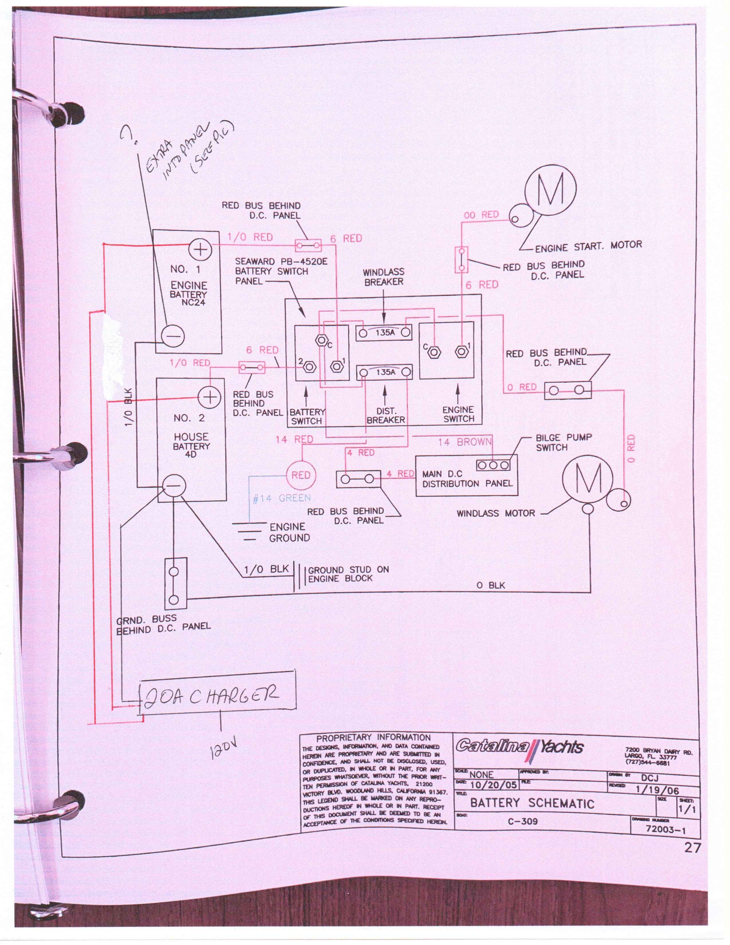
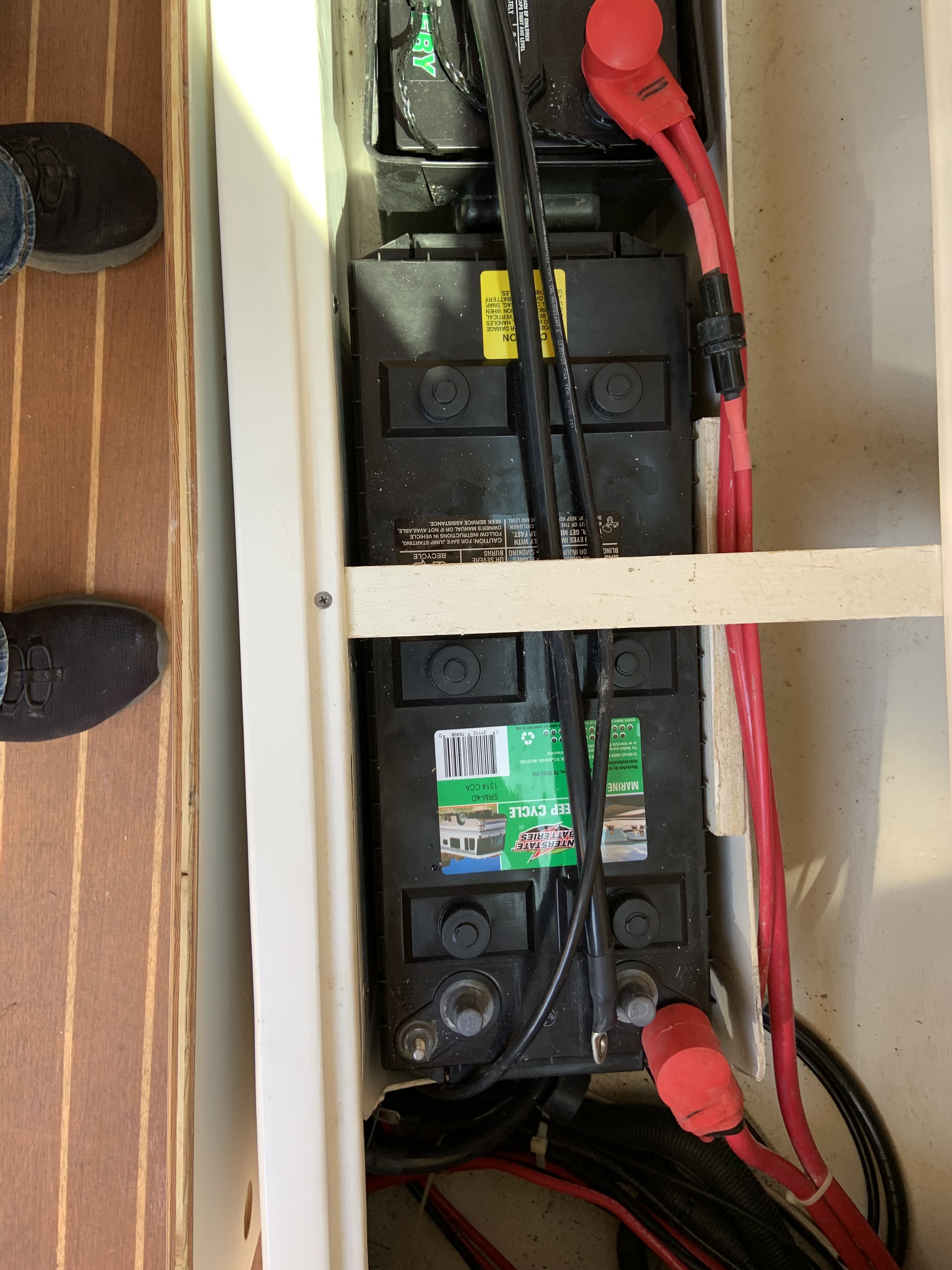
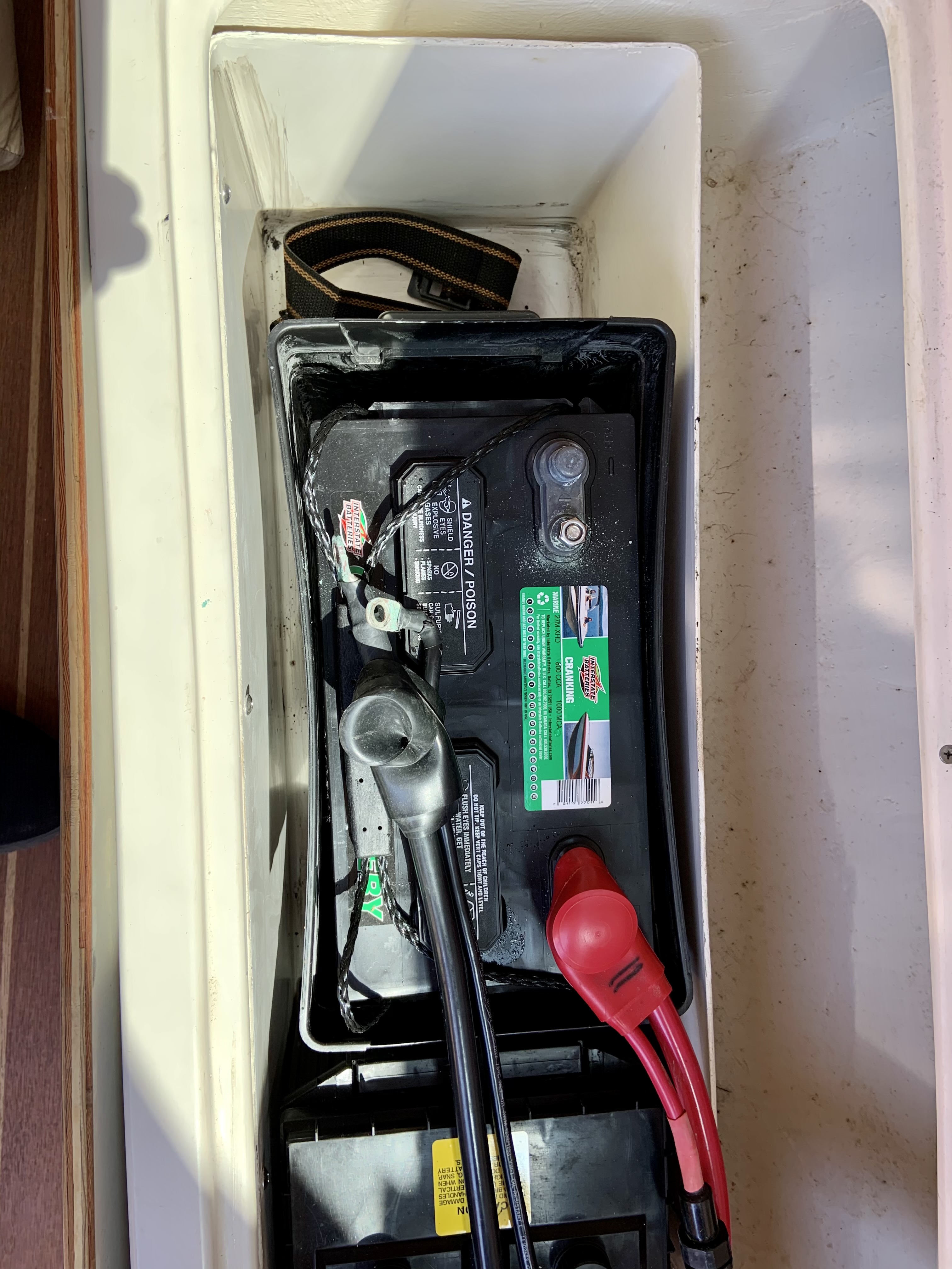
Confused about how to wire a Victron 702 on a boat - here is wiring diagram along with pictures of batteries.

Part of confusion is that I have an extra wire from starter battery into panel...wiring diagram attached along with pictures of batteries and a batter switch 1 (house), 2 (start) or both that I want to work as is does now after installation.

Thanks in advance!!!!


wiring diagram
2 |3000

Up to 8 attachments (including images) can be used with a maximum of 190.8 MiB each and 286.6 MiB total.

2 Answers
wkirby avatar image
wkirby answered ·

I presume that you primarily want to monitor the SOC of the House Battery.?
In that case, the shunt needs to be connected to the House Battery negative terminal. Remove all four wires from the negative terminal of the House Battery and connect those four wires to the terminal of the shunt which is labelled - LOAD AND CHARGER.
Then one 1/0 wire between the battery - terminal and other terminal of the shunt which is labelled - BATTERY ONLY.
Red wire from the shunt +B1 goes to the House battery and +B2 goes to the Start Battery.
In this configuration all current in or out of the House battery will be registered by the BMV.

I'm curious about the wiring of your 20A charger. There is a red wire coming from it and connecting both batteries positive terminals together. This would have the effect of the Seaward Battery Switch being permanently in the BOTH position, even when OFF is selected!

1 comment
2 |3000

Up to 8 attachments (including images) can be used with a maximum of 190.8 MiB each and 286.6 MiB total.

kaz avatar image kaz commented ·

Hi - thanks for your response - appreciate it - thanks - I understand the configuration of monitor - and I assume my switch Off, I, II, both will still work.

On the charger - if it helps there is two red wires coming from charger - 1 to each battery and 1 black wire to house negative - which then connects via cable to start negative....I Always assumes that separate reds keep the batteries seperate...I have always been confused by the black wire connecting the two batter negatives though - not sure why - but seems odd....

0 Likes 0 ·
Kevin Windrem avatar image
Kevin Windrem answered ·

I too raise concerns about that SMALLER wire interconnecting the charge with BOTH batteries at the same time. These smaller wires (as wkirby says) provide an end-run around the battery switch and are NOT protected from load currents. They could burn up with a heavy, sustained load. You need to install a switch so the charger only reaches one battery at a time.

Another observation: You have no independence between the house and engine systems. One or the other (or both in parallel) feeds ALL loads. Normally, loads are separated between engine and house and the battery switch ties the two batteries together only for emergency situations. The engine's alternator typically only charges the engine battery and house battery charging comes from other sources (solar, DC-DC charger from the engine battery, etc.).

1 comment
2 |3000

Up to 8 attachments (including images) can be used with a maximum of 190.8 MiB each and 286.6 MiB total.

kaz avatar image kaz commented ·

Thanks! Appreciate your response - sometimes my mechanic leaves off the wire that goes between both negative terminals of batteries - I assume so that they are separated as you mention and then only house battery charges with the charger - oddly when that wire is connected my switch between off, I,II and both - seems to work among batteries - there is also a small volt tester for battery I and II (toggles between them) on my panel...not sure which battery my alternator charges - but it seems like both as well...all very confusing - but this is how Catalina wired it out of the shop....

0 Likes 0 ·

Related Resources

Additional resources still need to be added for this topic