question

tooke avatar image
tooke asked

Multiplus powerassist on both legs safe?

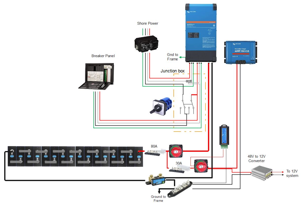
There's a popular Youtube channel that has given instruction on configuring a manual switch to allow powerassist on both legs in a 50 amp RV with a Multiplus 12/3000/120 . https://www.youtube.com/watch?v=gbKBoIvXNPA

The wiring diagram is here https://allaboutrvsinfo.com/wp-content/uploads/2021/02/50-amp-rv-manual-switch-as-builts.pdf

The below comment from a viewer states that this is unsafe. Is it?


"Looking at your 50 amp solution. A 50 amp RV has two 120 volt AC 50 amp circuits.. The wiring is hot1-neutral-hot2 and a ground. Note that the voltage across the hot wires of hot1 and hot2 is 230 volts AC. The voltage across hot1 and neutral is 120 volts AC. The same is true of hot2 and neutral. However, the AC phase of hot1 and hot2 are opposite, the two cancel each other out on the neutral line. Your proposed switch is putting AC voltage across both hot1 and hot2 in the same phase. This is not safe and will cause the neutral to have a voltage and current when the loads across hot1 and hot 2 are different. Too much of a difference and the wares can heat up excessively. Too much heat and you can damage the wire insulation which could result in shorting and possible fire. I strongly suggest you have this switched wire configuration reviewed by a qualified electrical engineer familiars with 50 amp RVs, before promoting it as a single inverter 50 amp solution. As an Registered RV Tech and RV inspector I do not recommend wiring any RV in this manor."

MultiPlus Quattro Inverter Charger
2 |3000

Up to 8 attachments (including images) can be used with a maximum of 190.8 MiB each and 286.6 MiB total.

3 Answers
mbiker avatar image
mbiker answered ·

Hi tooke,

I would agree with the RV Tech's comments if you are enabling more than 50A total of single-phase current to flow. The reasoning is that the neutral wiring in your standard RV distribution box is most likely sized for safely handling 50A max. That is the maximum sustained current that you would normally see when you're connected to shore power and drawing 50A one of your two legs and nothing from the other. If both legs were pulling 50A they would cancel at the neutral and it would see 0A.

If you limit the total single-phase current that you are enabling across the two legs (ie. the sum of the single-phase current that could be drawn on both of the legs) to be <= 50A then you won't be exceeding the safe current carrying capacity of your neutral.

Regards, Mike

2 |3000

Up to 8 attachments (including images) can be used with a maximum of 190.8 MiB each and 286.6 MiB total.

Kevin Windrem avatar image
Kevin Windrem answered ·

I too believe this is unsafe. There are two issues:

  1. Separate shore and Multi neutrals
  2. Increased current between the Multi's AC output and the RV Breaker Panel

The neutral problem is the most serious.

When the Transfer Switch is set in the normal mode, power to the "black" leg flows through the Multi and power for the "red" leg does NOT. When the Multi's AC input relay is closed, current for both the black and red legs flows through the Multi. This is probably against most electrical codes.

When the input relay opens, there is NO CONNECTION between the neutral coming from shore power/generator to the neutral in the power distribution panel. This is serious since there is no return path for "black" loads and black load voltage will be undefined (hopefully 0 but not guaranteed).

The only workable solution is to add a second neutral bus bar to the power distribution panel and switch the black leg's neutral along with the black leg.


The second problem is increased current due to power assist.

When the Multi's output is powering both legs of the power distribution panel, the total load current can exceed 50 amps in both the hot leg up stream of the Transfer Switch and the neutral.

Power assist adds to the available shore power, so up to 75 amps is available at the Multi's AC output(s). The solution is to increase wire size between the Multi's output through the switch and into the power distribution panel for both the hot and neutral legs. #4 60 degree C wire will handle 70 amps or 85 amps fro 75 degree C wire. Even #6 90 degree C wire will handle 75 amps but this means any wires in the same vicinity would also need to be rated for 90 C.

Here is a drawing that I feel is the safest way.

50 amp inverter changeover.pdf


2 |3000

Up to 8 attachments (including images) can be used with a maximum of 190.8 MiB each and 286.6 MiB total.

steven-recio avatar image
steven-recio answered ·

Hi @Kevin Windrem,

I too was concerned about the neutral issue you described. Is there a reason we can't just tie all the neutral legs together and bypass the Victron input switch for the neutral? The input switch can still open up line to disconnect from Shore Power, but you would maintain the Neutral connection. Only issue I can think of is if the Victron is measuring currents on both Line and neutral and expecting them to match. See below drawing:

48V_system.JPG


48v-system.jpg (96.1 KiB)
1 comment
2 |3000

Up to 8 attachments (including images) can be used with a maximum of 190.8 MiB each and 286.6 MiB total.

Kevin Windrem avatar image Kevin Windrem commented ·
I can't speak to where current measurement is done. If it is done on the neutral leg then you can't tie them together. If done on the hot legs tying the in and out neutrals together won't affect current measurements.

However, the neutral disconnect at the AC input relay may be mandated by electrical codes.

0 Likes 0 ·