question

drnitrox avatar image
drnitrox asked

Connecting 1-wire sensors ds18b20 to venus os on a raspberry 4

Hello all from a new member of this community.

is there anyone who can help me. I didn´t find an answer to my problem.

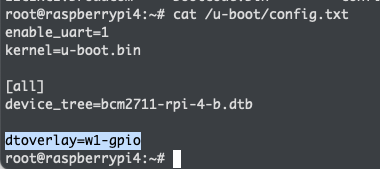
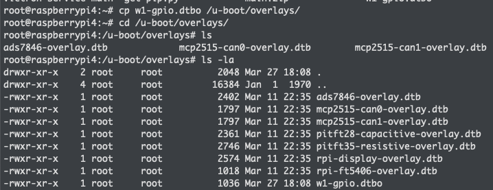
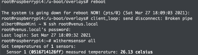
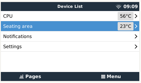
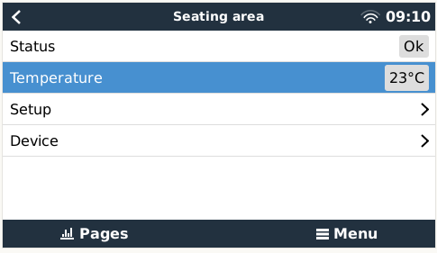
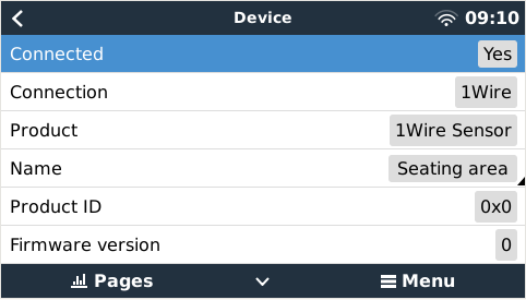
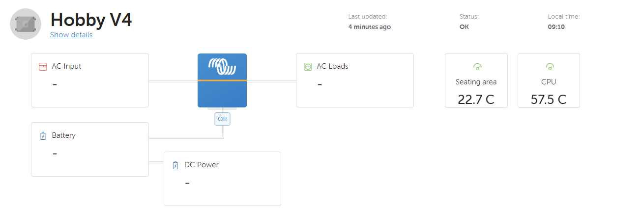
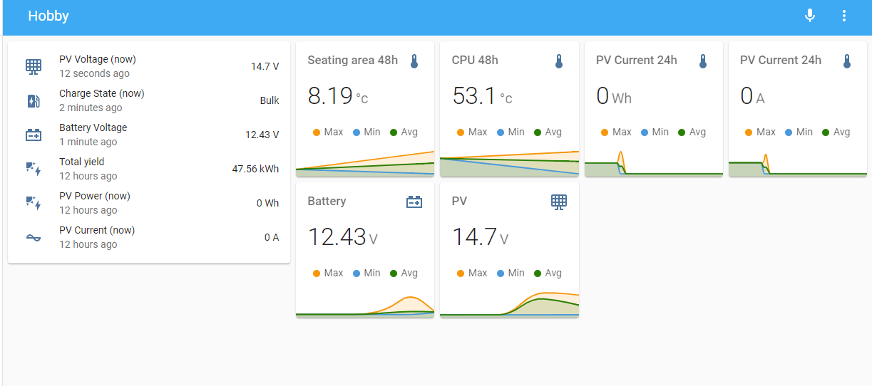
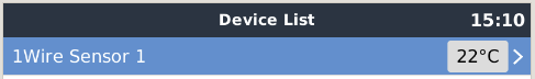
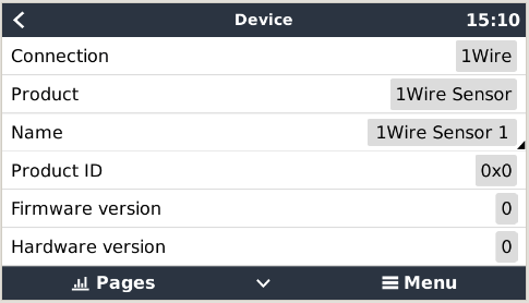
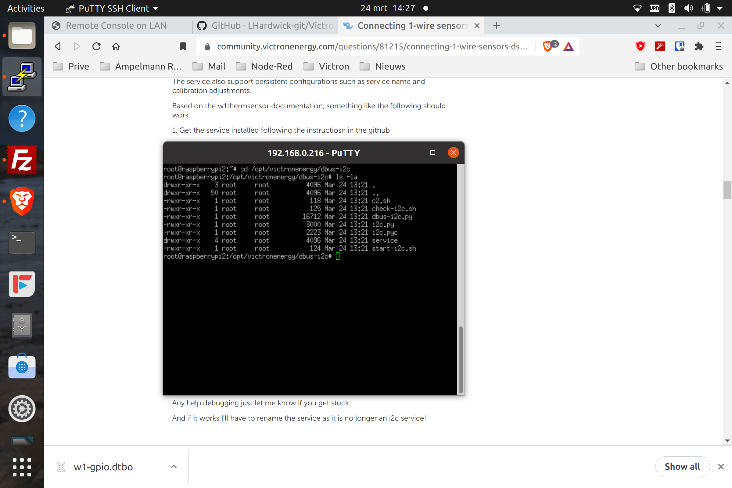
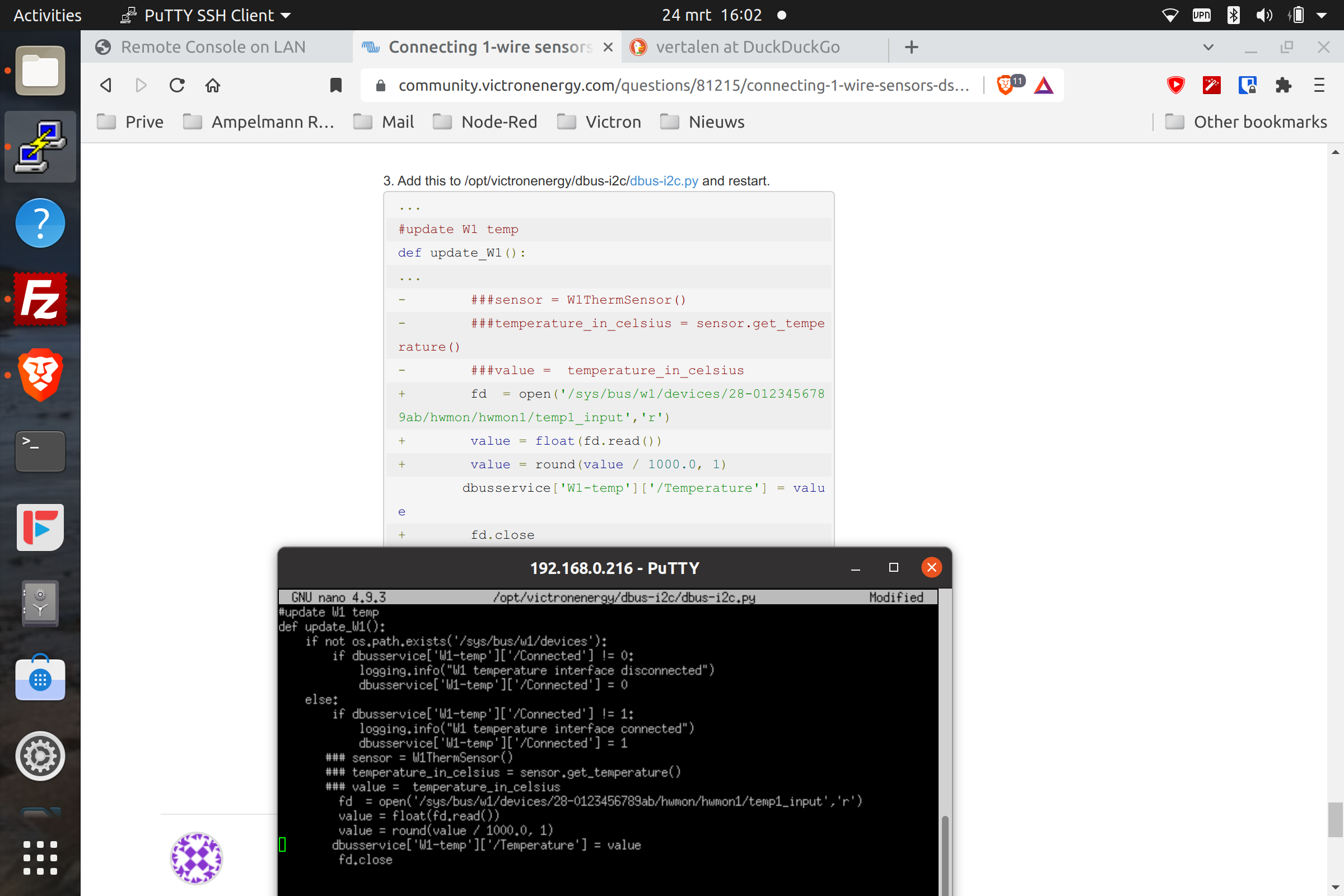
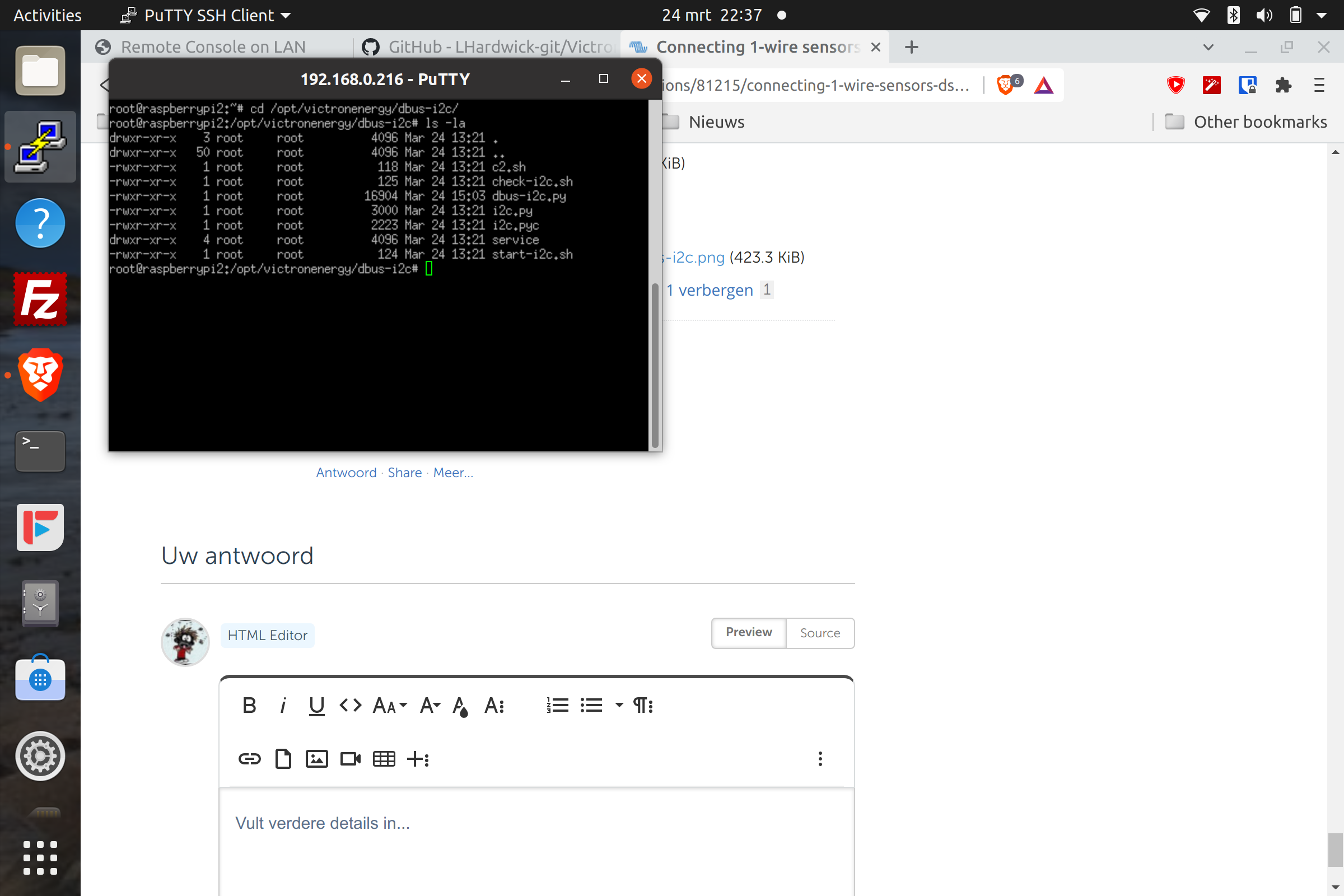
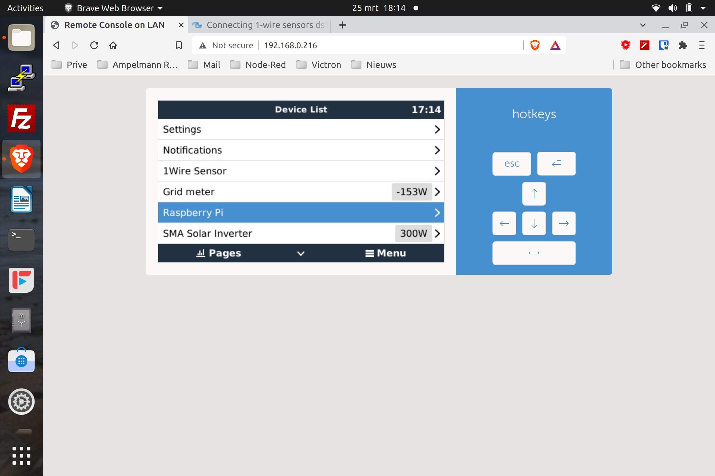
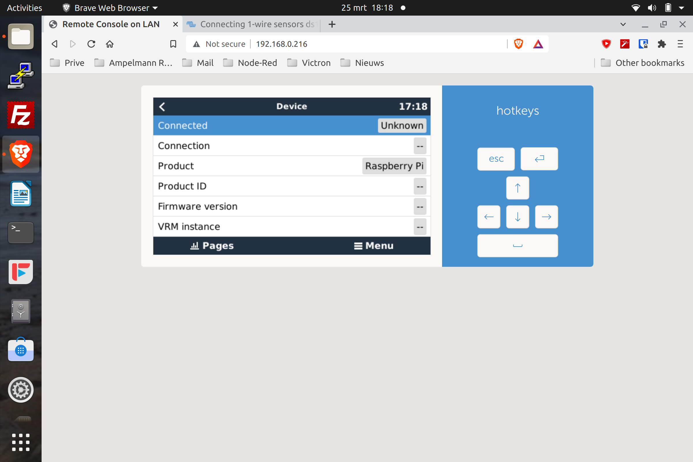
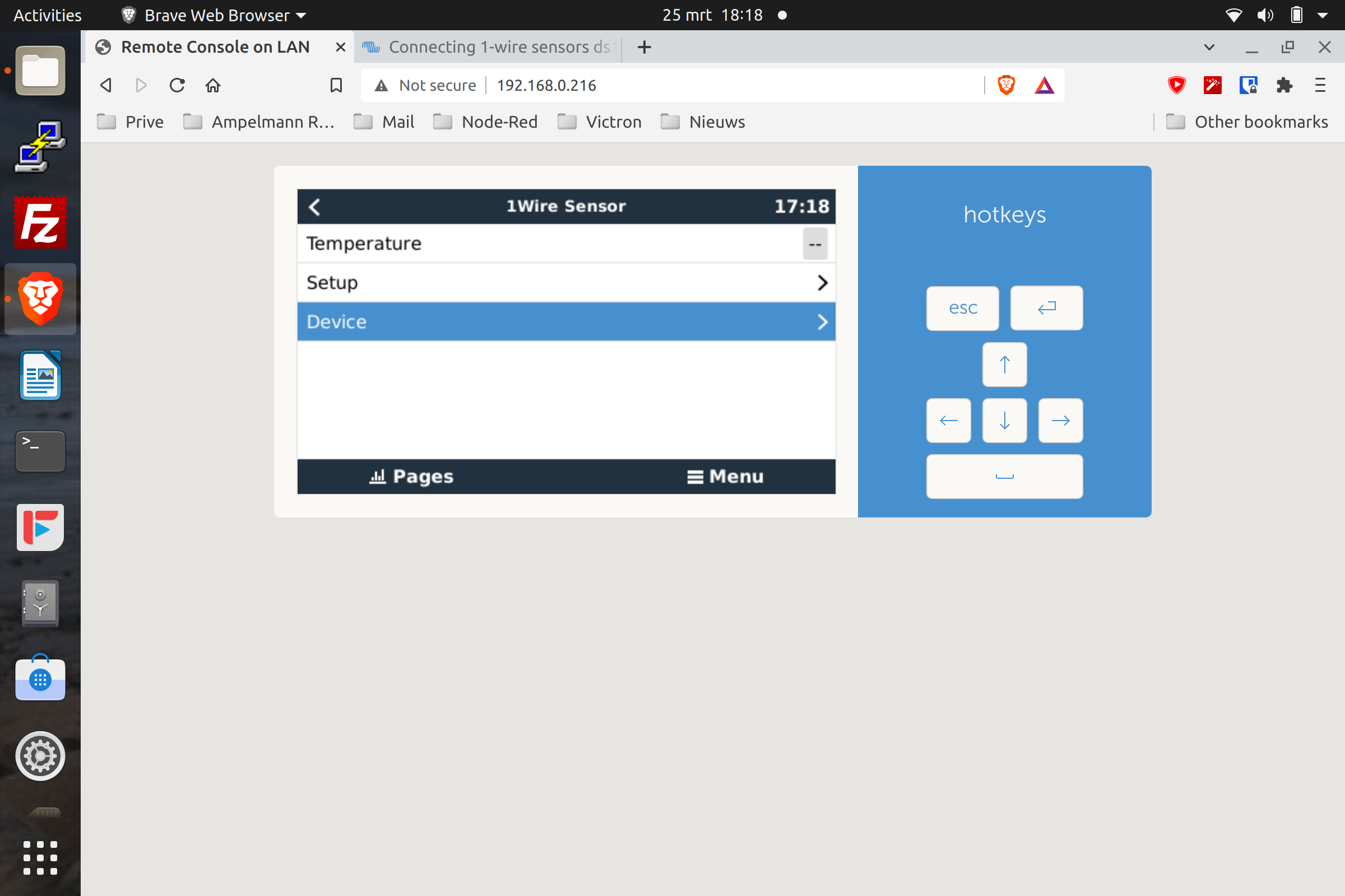
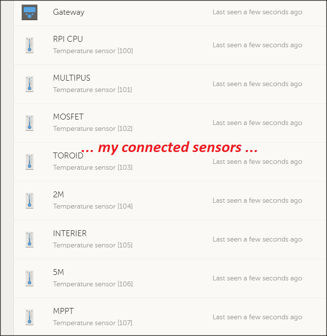
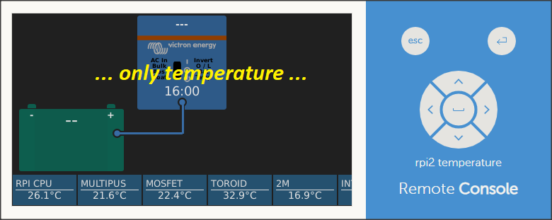
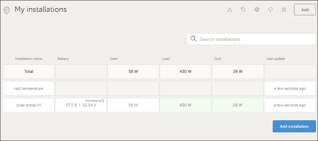
I am starting with a raspberry 4 and venus os and try to connect 1-wire sensors ds18b20 for temperature. But I don´t bring it to work, not with SignalK and also not with nodered.

I would be very happy if there is someone who has an answer for me.

Thanks a lot in advance and best regards from Germany.

temperature
2 |3000

Up to 8 attachments (including images) can be used with a maximum of 190.8 MiB each and 286.6 MiB total.

20 Answers
dirkmuc avatar image
dirkmuc answered ·

Hello,

You could try to install the Python libraries via pip and then to see if you can get the sensor readings on the console.

pip install w1thermsensor==1.3.0

The version 1.3 its the last one for Python 2.

Good luck.

Dirk

2 |3000

Up to 8 attachments (including images) can be used with a maximum of 190.8 MiB each and 286.6 MiB total.

drnitrox avatar image
drnitrox answered ·

Hello,

thanks for your hint. As a newbie to that all I will try to find out how to do that.

Thanks a lot.

Hans-Werner

2 |3000

Up to 8 attachments (including images) can be used with a maximum of 190.8 MiB each and 286.6 MiB total.

drnitrox avatar image
drnitrox answered ·

Hello Dirk,

it doesn´t work with that hint. I get "-sh: pip: command not found".

I think I have to activate the 1-wire for the Pi but i don´t know how do to that in Venus OS. Perhaps there is someone who knows it and can help.

Thanks a lot.

Hans-Werner

2 comments
2 |3000

Up to 8 attachments (including images) can be used with a maximum of 190.8 MiB each and 286.6 MiB total.

dirkmuc avatar image dirkmuc commented ·

you have to install pip first.

curl https://bootstrap.pypa.io/pip/2.7/get-pip.py -o get-pip.py

and then

python get-pip.py


0 Likes 0 ·
drnitrox avatar image drnitrox dirkmuc commented ·

Thanks. I will try that.

0 Likes 0 ·
berteh avatar image
berteh answered ·

Hello, I just thought I would post here since I was strugling with this for a few hours today.


I did the steps earlier in the post here but got no results from that, I almost gave up and installed raspian to try it one more time there just to make sure my sensor wasn't at fault, but it worked fine over there so i grabed the overlay file from there and transplanted it to the venus install and that worked :)


Steps are as follows:

Add this line to /u-boot/config.txt

dtoverlay=w1-gpio

So my config.txt looks like this now:

1616869627259.png

Copy the overlay from raspian, store it on my machine and put it back, since I'm on a mac I used scp for this but it could just as well been done from a file manager program such as winscp if you are on windows.

1616870150437.png


Move the overlay file to the correct folder

/u-boot/overlays

1616870629098.png


Rebooted and hey presto it worked :)

1616870771291.png


and although I haven't got it working in the dashboard yet I'm happy I just got it to display anything at all :')

If anyone is interested in getting the overlay file without the raspian install part just hit me up here or in a pm and i'll email it to you ;)


1616869627259.png (14.3 KiB)
1616870150437.png (22.5 KiB)
1616870629098.png (55.9 KiB)
1616870771291.png (31.9 KiB)
15 comments
2 |3000

Up to 8 attachments (including images) can be used with a maximum of 190.8 MiB each and 286.6 MiB total.

mvader (Victron Energy) avatar image mvader (Victron Energy) ♦♦ commented ·

Nice!

0 Likes 0 ·
laurenceh avatar image laurenceh commented ·

Nice - So my project here should be all you need to get it running on the console and the VRM as soon as you have the python library working. There are lots of hints of how do do it on this thread where people have described adding other i2C devices.

https://community.victronenergy.com/questions/58792/raspberry-pi-3b-heat-temperature.html

And here is a link to github where all the files you need are stored.

https://github.com/LHardwick-git/Victron-Service

What is it ?

This is a service that runs automatically on Venus OS and create a number of new services to read temperatures and Humidity from i2C but should easily to extend using the 1 wire python library. The service publishes the data to the Venus D-Bus from where it is automatically displayed in the console, on the VRM and is available to Node Red.

The service also support persistent configurations such as service name and calibration adjustments.

Based on the w1thermsensor documentation, something like the following should work:

1. Get the service installed following the instructiosn in the github

Import the W1ThermSensor libray near the start of the code (dbbus-i1c.py)

2. Create add a new temperature service using the models that are already there:

Something like:

dbusservice['W1-temp']     = new_service(base, 'temperature', '1Wire',      'W1 Device 1',  0, 25, 7)

You will need to adjust the last three parameters which are the device id, instance and settings id, let me know if you need help with that.

4. Create a new update routine (easiest to copy the CPU temperature code) call this update_W1():

5. Take out the bit reading the CPU temperature and insert the W1 reading line.

sensor = W1ThermSensor()
temperature_in_celsius = sensor.get_temperature()

NB it would be good practice to make the sensor global and not recreate the object every time you do an update.

6. add a line to the update routine to call the update_W1

Restart the service.

Any help debugging just let me know if you get stuck.

And if it works I'll have to rename the service as it is no longer an i2c service!


0 Likes 0 ·
berteh avatar image berteh laurenceh commented ·

Thanks for this, just a heads up the temperature service cannot start with a number.

had to scratch my head for a while before I rememberd the log file :P

@40000000606b7b9d36630304 ValueError: Invalid bus name 'com.victronenergy.temperature.1Wire_id00': a digit may not follow '.' except in a unique name starting with ':'

renamed the dbus service to 'Wire' just for testing and it worked straight away :)


I submitted a pull request on github with the changes I made to dbus-i2c.py

Here is the modified version:

https://github.com/albertbm/Victron-Service/blob/main/dbus-i2c/dbus-i2c.py

0 Likes 0 ·
laurenceh avatar image laurenceh berteh commented ·

Well done glad it worked. I’ll have a look and accept the pull request when I have a moment this week. Any screenshots to show it working?

0 Likes 0 ·
berteh avatar image berteh laurenceh commented ·

Forgot those :D

here they are:

1617700197769.png

1617700212910.png

1617700230554.png


one from VRM, I have the pi on my desk at home and no victron devices connected at the moment so no voltages or charging stats are available as of now :)

1617700303016.png

and the last one from Grafana

1617700463125.png

1617700481417.png

0 Likes 0 ·
1617700197769.png (15.8 KiB)
1617700212910.png (14.6 KiB)
1617700230554.png (21.0 KiB)
1617700303016.png (41.9 KiB)
1617700463125.png (42.8 KiB)
1617700481417.png (37.9 KiB)
szwuntex avatar image szwuntex berteh commented ·

Thank you very much for the modified version of dbus-i2c.py!
It is working great!

0 Likes 0 ·
laurenceh avatar image laurenceh berteh commented ·

@berteh I found where to get the overlay file so have posted the answer here

wget https://github.com/PiNet/PiNet-Boot/raw/master/boot/overlays/w1-gpio-overlay.dtb


0 Likes 0 ·
berteh avatar image berteh laurenceh commented ·

@LaurenceH yeah sorry I saw the mention in ny inbox a few days ago and forgot to reply back :/

I see the file you shared is a .dtb while mine is a .dtbo, I don't know if there is a difference but here is my file for anyone interested if the other one does not work:

https://drive.google.com/file/d/1CNDbKNRkZoLnMI109RHzxa6OIOvYGT4Z/view?usp=sharing

0 Likes 0 ·
berteh avatar image berteh laurenceh commented ·

Everything has been working great so far but the dbus-i2c is registering the temp from both the rpi and 1w sensors to the same location in InfluxDB
(temperature/Temperature) the correct tree for this needs to be dbus-service/Device/Values. As you can see it in this picture the graph jumps from rpi to the other sensor and back again, while this is not a big issue it would be nice to have this default graphing from venus working. as a workaround I have been collecting the temps via node-red and sending it back to the InfluxDB so i can correctly graph it in grafana


I'm not really seeing where we would seperate different sensors so they would go the correct path.1618350850932.png


0 Likes 0 ·
1618350850932.png (153.3 KiB)
laurenceh avatar image laurenceh berteh commented ·

I would like to help if I can.

The dbus-i2c code allows you to specify a number of different things about the d-bus configuration of each service I would have a look at that and make sure that the id and instance numbers for your service are unique. In you code snippet above you have ID=0 and instance = 25.

Looking at it from the other point of attack there are other temperature readings in Venus OS. Depending on your platform you should have the two built in generic values instance 23 and 24. Are you able to plot those without them jumping between values?

We need to work out in what way InfluxDB thinks the rpi and 1W temperatures are values of the same thing.

Laurence

0 Likes 0 ·
berteh avatar image berteh laurenceh commented ·

I don't see any data on instance 23 and 24 in the influx data

I tried changing the values of the instance but it still reports back to InfluxDB with the same, here are some other screenshots showing the name of the sensor changeing between 1Wire and CPU both on custom name and connection

1618430500369.png


1618430411987.png


Might the issue be that the script as it is now is registering the same service identifier with two names?

1618442954147.png

1618443089900.png

Perhaps this is not a issue if the venus interface or vrm is used but is causing problems with the grafana+influx integration

0 Likes 0 ·
1618430411987.png (75.1 KiB)
1618430500369.png (92.0 KiB)
1618442954147.png (15.0 KiB)
1618443089900.png (72.1 KiB)
laurenceh avatar image laurenceh berteh commented ·

Here is what I see on my devices list for modbus services:

img-0346.jpg

img-0345.jpg

As you can see they are all com.victronenergy.temperature, they have to be this otherwise the console the VRM wont pick them up. All have different unit IDs, and it appears yours also have different IDs, so that should be fine. The "generic temperature inputs" are the in built Venus OS services, it would be interesting to see if you can plot these (even if there is nothing connected) or if you even have these services on your setup?

If you think that the com.victronenergy.temperature is the problem then you can always create a service (make changes in the dbus-i2c.py code) to publish a d-bus service with a different name. But my guess is that the Console (Venus GUI) wont even see the service if you do that.

I think as you say this needs to be considered a problem with grafana+influx, so we need someone with knowledge of those to point you in the right direction.

0 Likes 0 ·
img-0346.jpg (220.9 KiB)
img-0345.jpg (187.8 KiB)
berteh avatar image berteh laurenceh commented ·

Yeah, thanks. I did try publishing to a different service but as you said it was not picked up in the console.


This is a minor issue for me so I don't think I'll pursue it any further for the time being :)

The thought with grafana was having a local place to look up nice historical data but I've been experementing with having node-red publish these straight to my home-assistant instance that I have at home so it's much nicer to have just one app/site to get all the relevant info at a a glance, here are some screenshots from that experiment

1618484996644.png

1618485109977.png


The numbers are so low because this is a old PV i had laying around in the garage and hooked it up just for testing :)

0 Likes 0 ·
1618484996644.png (134.8 KiB)
1618485109977.png (78.8 KiB)
olafd avatar image olafd laurenceh commented ·

Hi


this Service is running:

https://github.com/LHardwick-git/Victron-Service


The cpu-Temp is displayed but no Temp from a 1-Wire-Sensor!


The 1-Wire-Sensor is on raspis GPIO4 <— is that right?


Should something started additionally?


How do I get a identifierID of the 1-Wire-Sensor?


Is there a description for Venus OS and 1-Wire somewere ?


Could someone give me some hints with 1-Wire-Sensors please?


Thanks


Hardware: Raspberry 3B+

Software: VenusOS-2.8.2-Large

0 Likes 0 ·
olafd avatar image olafd olafd commented ·

Hi

one 1WireSensor is working now.

2022-02-1wire-temp.png

2022-02-1wire-info.png

Changes for that:

1. Copy this overlay to /u-boot/overlays/

https://drive.google.com/file/d/1CNDbKNRkZoLnMI109RHzxa6OIOvYGT4Z/view?usp=sharing


source:

https://community.victronenergy.com/questions/81215/connecting-1-wire-sensors-ds18b20-to-venus-os-on-a-1.html


add this to /u-boot/config.txt, for [all] at EndOfFile:

# 1-Wire Temperatursensor, Daten an Pin 4
dtoverlay=w1-gpio,gpiopin=4

and

chmod a+x /u-boot/overlays/w1-gpio.dtbo


2. Find the 1WireID (28-xxxxxxxxxxxx)

ls /sys/bus/w1/devices/
28-0123456789ab  w1_bus_master1


3. Add this to /opt/victronenergy/dbus-i2c/dbus-i2c.py and restart.

...
#update W1 temp
def update_W1():
...
-        ###sensor = W1ThermSensor()
-        ###temperature_in_celsius = sensor.get_temperature()
-        ###value =  temperature_in_celsius
+        fd  = open('/sys/bus/w1/devices/28-0123456789ab/hwmon/hwmon1/temp1_input','r')
+        value = float(fd.read())
+        value = round(value / 1000.0, 1)
        dbusservice['W1-temp']['/Temperature'] = value
+        fd.close


Caution:

If there is no 1WireSensor connected, the Temp reading flashes.


Hope that helps.

0 Likes 0 ·
drnitrox avatar image
drnitrox answered ·

Hello berthe,

thanks a lot for your info. I will try that to get my system working. Could you please send me the overlay file without the raspian install?

Regards

Hans-Werner

2 |3000

Up to 8 attachments (including images) can be used with a maximum of 190.8 MiB each and 286.6 MiB total.

Marcel avatar image
Marcel answered ·

Hello @OlafD

I realized that just asking for a solution or help is not "done" I would like to point out that I did my homework and really really tried to get this working by myself. I I am out of options now and really could use some help with this.


So what I did and tried up till now to get it running:


Downloaded Venus OS 2.82 Large 30 and did a clean install on a raspberry pi 3B+.


Then installed Guimods Setup, and after that installed GUImods and shutdown manager. All running just fine. No problems.


Installed a root password and activated SSH in Venus OS.


Downloaded the ‘’dbus-i2cpy.zip’’ file from Kevin-Windrem (dbus-i2cpy.zip (5.6 KiB) and unzipped it.


Visited https://github.com/LHardwick-git/Victron-Service for the install manual. From there also downloaded the “dbus-i2c” files by pressing the green button.


This is a zip named: Victron-Service-main. Inside is the “dbus-i2c” directory that has to be copied to the Victron OS correct?
Replaced the “dbus-i2c.py” file inside the directory for the “dbus-i2c.py file version from Kevin-Windrem


Copied the downloaded directory (with the replaced “dbus-i2c” file) in: /opt/victronenergy

(see attachement: Screenshot copied sdbus-i2c directory and chmod.png)

screenshot-copied-sdbus-i2c-directory-and-chmod.png


Replaced step 3 from the manual with this:

mkdir /opt/service/dbus-i2c ccp -r /opt/victronenergy/dbus-i2c/service/* /opt/service/dbus-i2c/

Looks all okay to me. Directory was made and files are copied. File attributes are set correct?

(see attachement: Screenshot alternative for step 3.png)

screenshot-alternative-for-step-3.png


Downloaded this overlay: https://drive.google.com/file/d/1CNDbKNRkZoLnMI109RHzxa6OIOvYGT4Z/view?usp=sharing

and copied it to: /u-boot/overlays/

Checked it, and the file is in /u-boot/overlays and it has the execute attribute set

(see attachement: Screenshot overlay file and attribute.png).

screenshot-overlay-file-and-attribute.png


Added the stuff below to: /u-boot/config.txt, (did not fully understand what “for [all] at EndOfFile” means, but I think I did it correct.

# 1-Wire Temperatursensor, Daten an Pin 4 
dtoverlay=w1-gpio,gpiopin=4

(see attachement: Screenshot uboot-config_txt.png)

screenshot-uboot-config-txt.png


Found the 1wireID with: ls /sys/bus/w1/devices/

(see attachment: Screenshot 1wireID.png)

screenshot-1wireid.png


Then I did: nano /opt/victronenergy/dbus-i2c/dbus-i2c.py to change the file as shown in this:


...

  1. #update W1 temp

  2. def update_W1():

  3. ...

  4. -###sensor = W1ThermSensor()

  5. -###temperature_in_celsius = sensor.get_temperature()

  6. -###value = temperature_in_celsius

  7. + fd = open('/sys/bus/w1/devices/28-0123456789ab/hwmon/hwmon1/temp1_input','r')

  8. +value =float(fd.read())

  9. +value = round(value/ 1000.0,1)

  10. dbusservice['W1-temp']['/Temperature']= value

  11. + fd.close

(see attachment: Screenshot changed file opt_victronenergy_dbus-i2c_dbus-i2c dot py.png)

screenshot-changed-file-opt-victronenergy-dbus-i2c.png


So my questions are:


Which “dbus-i2c.py” file is the correct one? The one downloaded from: https://github.com/LHardwick-git/Victron-Service or one of the two versions from Kevin-Windrem?


Which “overlay” file must be used? There are different files mentioned in the thread.


I connected the DS18B20 sensor to GPIO pin 4. Vcc at 3.3Volts. GND connected and a 4.7K resistor parallel over DATA and VCC. Should I use 5 Volt maybe?


After doing all of the above and a “Reboot” I see no change in the device list on the remote console. No 1wire sensor and no RPI CPU temp.


The manual states the following:


“There is a good chance the service will start, if not reboot your VenusOS device You can check in the file /var/log/dbus-i2c to see what is happening as the service starts up


It seems that if I do: cd var/log/dbus-i2c over SSH there is no such directory. So I can not check what’s happening. Where should I look for the log files?


When I SSH into: /opt/victronenergy/dbus-i2c to do: bash start-i2c.sh it shows a error:

svc: warning: unable to chdir to /service/dbus-i2c: file does not exist.

I checked, and that directory does not exist either!


So….what is it that I’m doing wrong or have forgotten? I really would like this to work because I want to monitor some temperatures for my heat-pump boiler. The only sensors that fit are those 1wire DS18B20 that I have. All hints, help and/or guidance are welcome!


Kind regards, and thanks in advance!


8 comments
2 |3000

Up to 8 attachments (including images) can be used with a maximum of 190.8 MiB each and 286.6 MiB total.

johnny-brusevold avatar image johnny-brusevold commented ·

@Marcel

Location of the files should be

/opt/victronenergy/dbus-i2c/

/opt/victronenergy/service/dbus-i2c/

0 Likes 0 ·
Marcel avatar image Marcel johnny-brusevold commented ·

Hi @Johnny Brusevold

Thanks for your quick response.

I did check /opt/victronenergy/dbus-i2c/ and it exists. It contains the dbus-i2c file that was downloaded. Checked also that the dbus-i2c.py file was exchanged for the one made by Kevin-Windrem.

(see attachment: Screenshot content opt_victronenergy_dbus-i2c.png)

screenshot-content-opt-victronenergy-dbus-i2c.png


I’m not sure about the /opt/victronenergy/service/dbus-i2c/. I did not have it on my system. I made it and placed also all the files in it from the dbus-i2c file. But it does not make any difference. Still no temp. reading in the remote console.

According to you….what should this directory contain?


Just wondering were this directory path comes from. I cant find it mentioned anywhere in all the posts. You are aware that I replaced step 3 in the manual for:


mkdir opt/service/dbus-i2c

cp -r opt/victronenergy/dbusi2c/service/* opt/service/dbus-i2c/


As far as I understand these commands make a directory called: opt/service/dbus-i2c

and then everything in: opt/victronenergy/dbusi2c/service/* is copied to: opt/service/dbus-i2c/


Is this step necessary or should I just use the original step 2?

So...am I mixing things up or do I missed something.


PS: can you tell me where to find the log files so I can check what is happening?

0 Likes 0 ·
johnny-brusevold avatar image johnny-brusevold Marcel commented ·

@Marcel

mkdir opt/service/dbus-i2c
cp -r opt/victronenergy/dbusi2c/service/* opt/service/dbus-i2c/

You lack /vicronenergy/ in the path


The right thing here is


mkdir /opt/victronenergy/service/dbus-i2c
cp -r /opt/victronenergy/dbus-i2c/service/* /opt/victronenergy/service/dbus-i2c/
0 Likes 0 ·
Marcel avatar image Marcel johnny-brusevold commented ·

@Johnny Brusevold


Hi Johnny.

I'm a bit confused here. In your previous answer you say:

The right thing here is

mkdir /opt/victronenergy/service/dbus-i2c
 cp -r /opt/victronenergy/dbus-i2c/service/* /opt/victronenergy/service/dbus-i2c/

But in the post on that other tread: https://community.victronenergy.com/comments/115736/view.html

you say this regarding replacing step 3

hould be

mkdir /opt/service/dbus-i2c
 cp -r /opt/victronenergy/dbus-i2c/service/* /opt/service/dbus-i2c/

But anyway….started all over again :)

Fresh install, but even with your suggestion regarding the installation path….still nothing! How important is it to do the steps in the correct order? I mean: what should I do first. Put the overlay file in place or install the dbus-i2c directory (with the dbus-i2c.py file from Kevin Wind-rem)


Am I correct that if everything went well you should see the device in the device list straight away after a reboot? Or should I activate some thing in the remote console?

Again….cant find any log files to check. I’m lost. Would an older version of Venus OS a option? Using 2.85 large 30 now.


Really appreciate your patience and effort to help me out! Can you tell me the exact version of Venus OS you are using? And also which other files? Still not giving up on this. Only wish I had some more computer skills!


Marcel

0 Likes 0 ·
johnny-brusevold avatar image johnny-brusevold Marcel commented ·

@Marcel

There have been some changes in the versions of venus-os, but now I run 2.82 large 30 with the same files that you use, installed in the folders that I referred to in the previous post, and it works perfectly. I have not tested or seen any 2.85 large 30 version, so I can not comment on that version.

To check if it has anything to do with rights, you can 'cd' into the directories and run a chmod a + x * and possibly set the correct rights afterwards


EDIT

Or you can clean up what you have already done and extract this file from ' / '

w1_cpu_temp

entered the serial number for your w1 sensor, but you can check if it is correct.

Also see that there are some differences in path to temp reading on different versions of venus-os

Then also check the path to 'temp1_input' in dbus-i2c.py

/sys/bus/w1/devices/28-0119213b729d/hwmon/hwmon2/temp1_input

Requires restart of pi

0 Likes 0 ·
Marcel avatar image Marcel johnny-brusevold commented ·

@Johnny Brusevold

I made a typo. My OS version is 2.82 Large 30. So the same one you use. Checked and double checked the execute attributes from all the mentioned files in dbus-i2c. They have a "X" for user, owner and others, so this should be ok.

Are you using GUImods? Maybe this can be a problem? I installed it for the shutdown function. Really like that!.

Two more questions. If I do bash check-i2c.sh it reports tha the proces is not found.

Can you tell me where the log file is stored. I realy want to have a look at that.

For now I will do a clean install again. If you are using the same OS version, use the same overlay file and have the same mods to the files then it should work for me to!

Anyway...will use the directory paths you mentioned:

  1. mkdir /opt/victronenergy/service/dbus-i2c
  2. cp -r /opt/victronenergy/dbus-i2c/service/* /opt/victronenergy/service/dbus-i2c/
0 Likes 0 ·
Marcel avatar image Marcel johnny-brusevold commented ·

@Johnny Brusevold


Now we are getting somewhere! I put your files in the correct directory's on my PI and it did (sort off) work!

I did see the RPI temperature (this was before a RPI reboot) but it seemed like the temp sensor in screen was switching on and off. Sort of flickering? The 1Wire sensor was also available in the device screen but according to that screen it it was disconnected.

After te reboot I see this in the device list:

screenshot-from-2022-03-25-18-14-51.png

This for the RPI temperatur:

screenshot-from-2022-03-25-18-17-56.png

screenshot-from-2022-03-25-18-18-21.png

And this for the 1Wire sensor:

screenshot-from-2022-03-25-18-18-30.png

screenshot-from-2022-03-25-18-18-41.png

It could be that I forget to remove something from the stuff that I altered. I also checked

/sys/bus/w1/devices/28-0119213b729d/hwmon/hwmon2/temp1_input

It's a bit different than mine

/sys/bus/w1/devices/28-0119213b729d/hwmon/hwmon1/temp1_input

If nothing else then I will do another clean install tomorrow. Or do you no what the problem could be?

Anyway...after struggling for 4 days there is finally some progress! Thank you so much for your time and effort. Again....it's much appreciated!

0 Likes 0 ·
Marcel avatar image Marcel Marcel commented ·

After a shutdown (so no reboot) everything is back to the old situation! So nothing to see at al in the device list in the remote control.

I have to re think this again!

UPDATE!!!!

Got it working! even after a re-boot and/or complete shutdown it keeps working. RPI temperature and 1Wire sensor temperature.

Not sure, but as far if I can determine with my knowledge all my copy stuff was ok. After the tip from @Johnny Brusevold to check the path to the temp reading it all worked! I'm so happy now.

Johnny.....your the man! thank you so much for all your help, guidance,tips and especially patience! Just helping out a NOOP.

Thanks again for all your time and effort. I would never got this running without you.

0 Likes 0 ·
rikkert-rs avatar image
rikkert-rs answered ·

Hello for everyone who is still interested in 1 Wire Sensors in Venus OS, I have a first version of the Repo from LHardwick converted in an Setup Helper Package from Kevin Windrem

https://github.com/Rikkert-RS/VenusOS-TemperatureService

3 comments
2 |3000

Up to 8 attachments (including images) can be used with a maximum of 190.8 MiB each and 286.6 MiB total.

Philip avatar image Philip commented ·
Rikkert, I really like your solution, it works great.

Question: how to turn off the raspi CPU temperature, I don't really need it.


0 Likes 0 ·
sf777 avatar image sf777 commented ·

@Rikkert-RS

Hi.

Could you help me with connecting 4 pieces of DS18b20? I use rpi with venus os. I used your project "VenusOS-TemperatureService". The sensor temperatures are only displayed for about an hour. Then they disconnect. Only turning off the rpi completely or disconnecting the DS18b20 from power will help.

What version of venus os should I use to make it work reliably?

Well thank you...

0 Likes 0 ·
rikkert-rs avatar image rikkert-rs sf777 commented ·

@sf777

Hello, the stability does not come from the driver. If the sensors are detected, it is usually due to the wiring or the sensors themselves.

Goto this issue on Github for some troubleshooting with wiring.
There are also further links to 1Wire and how to connect it correctly

https://github.com/Rikkert-RS/VenusOS-TemperatureService/issues/11


best regards Rikkert-RS

1 Like 1 ·
Holger Watermann avatar image
Holger Watermann answered ·

super, this runs well. But i would like to disable the 1 Wire untill i really put in the Sensor at pin 4.


thanks a lot, so we don´t have to activate cpu temp after every update. (only the root name ;-)


holger

2 |3000

Up to 8 attachments (including images) can be used with a maximum of 190.8 MiB each and 286.6 MiB total.

sf777 avatar image
sf777 answered ·

Hi. I am trying to connect to venus os which is in rpi four DS18B20 but without success. I tried it, on RPI2, RPI3 and RPI4, still failure. After the restart, the sensors work for 1 hour and then disconnect.

Which RPI should I use and what procedure?

well thank you

2 |3000

Up to 8 attachments (including images) can be used with a maximum of 190.8 MiB each and 286.6 MiB total.

sf777 avatar image
sf777 answered ·

Is there really no one who can help?

2 |3000

Up to 8 attachments (including images) can be used with a maximum of 190.8 MiB each and 286.6 MiB total.

sf777 avatar image
sf777 answered ·

@rikkert-rs

Thanks for the proper direction. I finally found the problem. It took a long time but I didn't give up. One of the sensors was faulty. Simply, after about an hour, one DS18B20 turned off or shorted. Now (on raspberry pi2) everything is ok. :-)

I have a request for you. I plan to use this device to monitor the temperature of individual components. I will not connect any battery or PV panels to it. I have a Cerbo GX for that. :-) Would it be possible to adjust it so that only sensor temperatures are displayed in the Remote Colsole?

I am attaching some screenshots.

0427-2002-2024.png

0428-2002-2024.png

0429-2002-2024.png

Thank you very much.


0427-2002-2024.png (42.5 KiB)
0428-2002-2024.png (30.6 KiB)
0429-2002-2024.png (32.8 KiB)
2 |3000

Up to 8 attachments (including images) can be used with a maximum of 190.8 MiB each and 286.6 MiB total.

bigbadbob76 avatar image
bigbadbob76 answered ·

Yes, it is possible.

You would need to edit /opt/victronenergy/gui/qml/overviewhub.qml to remove the unwanted inverter and battery, then move the temperature boxes around so they all fit in the available space.

You have a different venus version than me though so I can't give you a step by step guide, but back up your original overviewhub.qml file first so you can go back to it, then change one thing at a time until you get it how you want it, don't try and do it all in one go or you won't know what changes have screwed it up when the screen goes white on you.

2 |3000

Up to 8 attachments (including images) can be used with a maximum of 190.8 MiB each and 286.6 MiB total.

sf777 avatar image
sf777 answered ·

@Bigbadbob76

Thank you for your reply. My version of venus is v3.14. Tomorrow I will try to change the file as you write.0430-2002-2024.png

This is my file "OverviewHub.qml"

OverviewHub.qml.rar.zip


2 |3000

Up to 8 attachments (including images) can be used with a maximum of 190.8 MiB each and 286.6 MiB total.

bigbadbob76 avatar image
bigbadbob76 answered ·

OK, i'll suggest a few things for you to try, no promises they will work as I cannot test them on my system but they will give you a starting point.

to hide the inverter-

Multi {
id: multi
anchors {
horizontalCenter: parent.horizontalCenter
top: parent.top; topMargin: 5
}

visible: false //insert this line
}


to hide the battery-

Battery {
id: battery

soc: sys.battery.soc.valid ? sys.battery.soc.value : 0

anchors {
bottom: parent.bottom; bottomMargin: 5;
left: parent.left; leftMargin: 10
}
values: Column {
width: parent.width

TileText {
// Use value here instead of format() because format adds the unit to the number and we
// show the percentage symbol in a separated smaller text.
text: sys.battery.soc.value === undefined ? "--" : sys.battery.soc.value.toFixed(0)
font.pixelSize: 40

Text {
anchors {
bottom: parent.bottom; bottomMargin: 9
horizontalCenter: parent.horizontalCenter; horizontalCenterOffset: parent.paintedWidth / 2 + 5
}
visible: sys.battery.soc.valid
text: "%"
color: "white"
font.bold: true
font.pixelSize: 12
}
}
TileText {
text: sys.battery.power.format(0)
}
TileText {
text: sys.battery.voltage.format(1) + " " + sys.battery.current.format(1)
}
}

visible: false //insert this line
}

2 |3000

Up to 8 attachments (including images) can be used with a maximum of 190.8 MiB each and 286.6 MiB total.

bigbadbob76 avatar image
bigbadbob76 answered ·

As you are using guimods you might need to edit overviewhubEnhanced.qml instead of overviewhub.qml. please post that file too.

1 comment
2 |3000

Up to 8 attachments (including images) can be used with a maximum of 190.8 MiB each and 286.6 MiB total.

sf777 avatar image sf777 commented ·

"gui mods" is not a requirement. If it will be easier without it, I will remove it.

0 Likes 0 ·
sf777 avatar image
sf777 answered ·

Thanks again for helping me with this.

I am attaching the "OverviewHubEnhanced" file.

OverviewHubEnhanced.zip

My thinking is that it could be used to monitor the temperature of basically anything for relatively little money. Just use raspberry pi with venus os and lcd. Add a new installation in your account and you will see real-time temperatures as well as history.


2 |3000

Up to 8 attachments (including images) can be used with a maximum of 190.8 MiB each and 286.6 MiB total.

sf777 avatar image
sf777 answered ·

@Kevin Windrem

Hi.

Don't want to join? :-)

Maybe you could help me with that.

2 |3000

Up to 8 attachments (including images) can be used with a maximum of 190.8 MiB each and 286.6 MiB total.

sf777 avatar image
sf777 answered ·

@Bigbadbob76

So far I have managed this.

0432-2102-2024.png

I can't move anymore. The time can stay there, but I can't distribute the temperatures over the entire area.


0432-2102-2024.png (13.4 KiB)
2 |3000

Up to 8 attachments (including images) can be used with a maximum of 190.8 MiB each and 286.6 MiB total.

sf777 avatar image
sf777 answered ·

Here is the modified file.

OverviewHubEnhanced_MOD.zip


2 |3000

Up to 8 attachments (including images) can be used with a maximum of 190.8 MiB each and 286.6 MiB total.

sf777 avatar image
sf777 answered ·

I got here so far. I am attaching some screenshots.

0433-2202-2024.png

0434-2202-2024.png

0435-2202-2024.png

I changed the size and position of the hour.

I changed the position of the temperature indicator from the sensors.

I can move the temperatures from left to right. Well, I would like them in two or three rows. I don't need rpi temperature there.

I can't move anymore. :-( Can anyone help?


0433-2202-2024.png (13.4 KiB)
0434-2202-2024.png (13.2 KiB)
0435-2202-2024.png (19.1 KiB)
2 |3000

Up to 8 attachments (including images) can be used with a maximum of 190.8 MiB each and 286.6 MiB total.

Related Resources

Additional resources still need to be added for this topic