question

bjorn-n avatar image
bjorn-n asked

MultiPlus-II grid setpoint without external grid meter

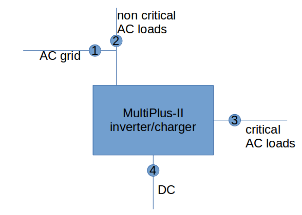
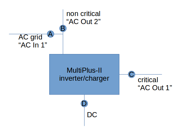
I have a MultiPlus-II that is tied to the AC grid. I recently connected it to a GX (on a Raspberry Pi 3). I already changed the configuration from Virtual Switch to the ESS Assistant. I have no grid metering connected to the GX or to the MultiPlus-II. For the moment, I want to control it manually.

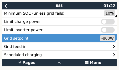
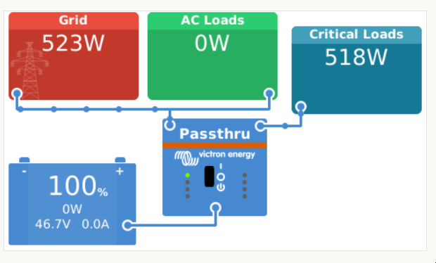
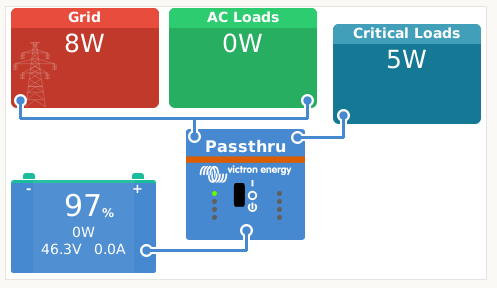
Even though the grid setpoint is set to -800W to feed 800W back into the grid, it doesn't seem to have any effect and the MultiPlus-II stays in Passthru mode.

screenshot-at-2021-02-28-01-22-48.png

2021-02-27-20-57-27-remote-console-on-lan-mozilla.png

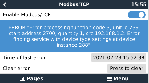
I have searched this forum and found one similar post (https://community.victronenergy.com/questions/48014/multiplus-ii-gx-stays-in-passthru-state.html) that ended up to be a bug/singularity.

Mine was cause because of a GX misconfiguration.

See https://www.victronenergy.com/media/pg/Energy_Storage_System/en/faq.html Q4

In ESS, the conditions for the VE.Bus system to be in pass-through (ve.bus state: passthru) are:

  1. When the GX device is no longer receiving data from the grid meter. Note that this is only for systems that are configured to have an external grid meter. See the Settings → ESS → Control without grid-meter setting.

  2. ...

So the solution seems to be simple... Simply adjust the settings.screenshot-at-2021-02-28-01-29-44.png

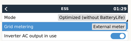
However, there is no "without grid-meter" option in Settings > ESS > Grid metering

screenshot-at-2021-02-28-01-30-31.png

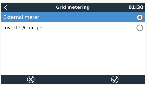
The "without grid-meter" option is in fact the inverter/charger option. This is quite confusing. After setting it to Inverter/Charger, the Grid setpoint works as intended.

screenshot-at-2021-02-28-01-33-02.png

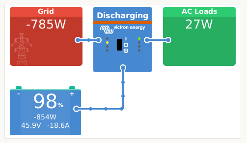
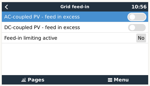
So far so good. But as you can see in the last screenshot, the "critical loads" box disappeared.

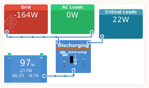
After I changed the grid metering setting back to external meter, I got the critical loads box back for a short time while it was also feeding energy into the grid.

screenshot-at-2021-02-28-01-42-53.png

But then the feed in stopped. Because off course, the setting is wrong. And the register has not been written for 60 seconds.

screenshot-at-2021-02-28-01-46-20.png

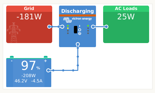
Correcting the setting feeds energy into the grid again, but then I loose my "critical loads" box again.

1614473272561.png

I have been switching back and forth a couple of times:

- if I set it to External meter, the critical loads box shows, but grid setpoint does not work

- if I set it to Inverter/Charger, the critical loads box is hidden, but grid setpoint does work.

This looks like a (reproducable) bug in the interface to me. Can someone confirm? Or point out what I'm missing?


P.S.: in case someone notices in the screenshots, I changed the Grid setpoint from -800W to -200W during the troubleshooting.

Multiplus-IIESS
2 comments
2 |3000

Up to 8 attachments (including images) can be used with a maximum of 190.8 MiB each and 286.6 MiB total.

seb71 avatar image seb71 commented ·

You charge the battery from the grid and then feed in from the battery to the grid?

I see no MPPT and no PV inverter.

0 Likes 0 ·
bjorn-n avatar image bjorn-n seb71 commented ·

Correct. There is no MPPT. There is no PV inverter visible to the MultiPlus-II.

To be 100% correct, the PV inverter is directly connected to the grid for the simple reason that the PV inverter's peak power exceeds the 3000 VA of my MultiPlus-II.

0 Likes 0 ·
3 Answers
jacola avatar image
jacola answered ·

Hi Bjorn, i had a very similar setup for 8 months and just now added enough inverters to go 'through' them.

I cannot tell you about the critical load question and why you lose that setting, but maybe my answer is helpful ..

I had several PV inverters (more power my victrons could handle), \loads (higher than what victron could handle). So i configured my system as 'grid assist' You can of course still connect critical loads.
Then i used ESS mode 3 (external control) and sent the grid setpoint(s) via modbus. That worked for this setup. However i decided to put ALL loads behind victron, so i upgraded to 6 MP-II 5000, load regulation (setpoints via modbus/tcp) is a very lame duck, due to comms timing, victron accepting only about one write per second (i might be wrong on this) and a limitation of 'no more load change than 400W/second'.

johannes


3 comments
2 |3000

Up to 8 attachments (including images) can be used with a maximum of 190.8 MiB each and 286.6 MiB total.

bjorn-n avatar image bjorn-n commented ·

Thank you Johannes. I am going the same route. I don't think I'll end up with 6 MP-II 5000 though. :-) Knowing the limitations of writing the grid setpoints via modbus/tcp beforehand is always a good thing. Split second timing isn't on my requirements list (yet). So it should do for the time being.

Currently still struggling with Modbus-TCP (using Python). I'm connected on port 502 but I haven't been able to read register 2700. Let alone write it...

I can trigger a lot of Modbus/TCP errors on the GX already :-)

screenshot-at-2021-02-28-15-55-16.png

But I digress...

0 Likes 0 ·
jacola avatar image jacola bjorn-n commented ·

beware, you need to use the right unit ids, this is a bit confusing. the 270x needs to be addressed on unit ID 100 ..

Have you considered to use MQTT ? might be easier, less load on your system and i have tested both, they seem to work equally well or badly :)

johannes


0 Likes 0 ·
bjorn-n avatar image bjorn-n jacola commented ·

Yes indeed, the first code block has no effect (even though it does not return an error. The second one has the desired effect.

from pyModbusTCP.client import ModbusClient
c = ModbusClient(host="192.168.1.12", unit_id=239, debug=True)
c.open()
c.read_holding_registers(37)
c.write_single_register(37, 800)
c.read_holding_registers(37)
c.close()

c = ModbusClient(host="192.168.1.12", unit_id=100, debug=True)
c.open()
c.read_holding_registers(2700)
c.write_single_register(2700, 800)
c.read_holding_registers(2700)
c.close()

I've read that the GX is a kind of gateway to whatever devices that are connected to it (such as the MultiPlus-II). And by design, it also to write certain values at least every minute to the MultiPlus-II (thus overwriting any values you write to theMultiPlus directly).

0 Likes 0 ·
kalito avatar image
kalito answered ·

The correct setting is the one you are using that is the inverter acts as the meter. There is also a setting on whether or not you have a PV inverter. I suspect you ought to set that. I am curious as to why you charge the battery with grid and then want to export back. What is the rationale?

7 comments
2 |3000

Up to 8 attachments (including images) can be used with a maximum of 190.8 MiB each and 286.6 MiB total.

bjorn-n avatar image bjorn-n commented ·

I assume the setting whether or not you have a PV inverter refers to the top one in the screenshot below.

screenshot-at-2021-02-28-10-56-50.png

The PV inverters are not connected to the MultiPlus-II because the PV inverter peak power exceeds the MutliPlus-II "AC Loads" power rating. So although there are is a solar installation and PV inverters, the MutliPlus-II does not "see" this component. Hence the "AC-coupled PV" setting is set to off.

The rationale: I have different energy tariffs depending on the day of the week and time of day. I want to balance (read: zero out) my energy consumption and production as much as possible using the MultiPlus-II and the battery. Because it is not "AC coupled", I have to "manually" set the grid set point to so the battery charges when there is excess solar energy (net production) and the battery discharges when there is net consumption.

I still wonder though why the interface does not show the seperate AC loads and critical loads when the Grid metering settings is set to "Inverter/Charger".


0 Likes 0 ·
seb71 avatar image seb71 bjorn-n commented ·
I still wonder though why the interface does not show the seperate AC loads and critical loads when the Grid metering settings is set to "Inverter/Charger".

If you have a PV inverter on "AC In" side of the Multiplus, then you should also have an energy meter.

0 Likes 0 ·
bjorn-n avatar image bjorn-n seb71 commented ·

From the documentation, in Mode 2, having a energy meter is not a must have. I have several energy meters on different parts of the "grid" side (as seen from the MultiPlus-II). These energy meters are not connected to the MultiPlus-II. These energy meters are connected to my home automation network that also includes solar PV inverter, electric water heater, electric car charger, etc...


The MultiPlus-II has two connections labeled "AC In". Power consumption is measured on both. See measurements points 1 and 2 in the picture. I've labeled 1 as AC grid and 2 as non critical AC loads.

Power is also measured on the "AC Out" connection. The so called "critical AC loads" side. That's measurement point number 3.

A fourth power measurement point is on the DC side.

screenshot-at-2021-02-28-12-01-43.png

So why on Earth does the interface properly display measurement points 1,2,3,4 separately (when set to External meter). But when I set grid metering to inverter/charger it adds up measurements on 2 and 3 and thus only showing three measurements:

  • 1 AC grid
  • 2+3 as "AC loads"
  • 4

I'm sorry, but I still don't see a reason why the interface adds up 2+3... I mean, screenshots clearly show it's capable of showing these values separately (when grid metering is set to External meter). Perhaps there should be a third configuration setting "No external meter"?

0 Likes 0 ·
seb71 avatar image seb71 bjorn-n commented ·
I have several energy meters on different parts of the "grid" side (as seen from the MultiPlus-II). These energy meters are not connected to the MultiPlus-II. These energy meters are connected to my home automation network that also includes solar PV inverter, electric water heater, electric car charger, etc...

Not sure what is the relevance.

The MultiPlus-II has two connections labeled "AC In".

No, Multiplus II does not have two AC In connections. Only one.

Quattro has two AC In connections.

0 Likes 0 ·
bjorn-n avatar image bjorn-n seb71 commented ·

You are right! MultiPlus-II only has one "AC In" connection (measurement point 1). It has two "AC Out" connections, one for non-critical loads (measurement point 2) and one for critical loads (measurement point 3).

The question still stands however: why does the interface add the power on non-critical and critical loads together (when grid metering is set to External meter)?

0 Likes 0 ·
Maciek Haranczyk avatar image Maciek Haranczyk bjorn-n commented ·

Maybe this scheme helps. It seems AC OUT1 and OUT2 are connected to the same inverter output so they are practically the same thing.6282-14aae2ba-75b5-4bbb-b112-f6046c2bac5d.jpeg

0 Likes 0 ·
kalito avatar image kalito bjorn-n commented ·

AC1 and AC2 are not exactly separate and only differ in that AC2 can be isolated. This isolation can be programmed via software (VEConfig Assistants). The feed to AC outlets is therefore common. My suspicion is that if set to meter the inverter looks at what is incoming and tries to match this on the outputs so the meter reads zero. I am assuming this logic still works even if there is no meter as such for as long as the setting is to meter. If it knows what is coming in then the measurements at ACs in relation to input can then be disaggregated.

Perhaps when set to inverter as meter the logic then doesnt seem to bother about disaggregation and merely notes the incoming and passes it on to the output as common. Its a good question as to why the split is not shown. I do not have anything on my AC2 so I have never bothered about seeing critical load.

I "discovered" the limitations of AC2 when I put water heater on it and thought it could be controlled separately. Alas under ESS (set to optimise battery life but only to use grid when set SOC is attained e.g 20%) I noticed that the none-critical load was being fed from battery with AC1.

The AC1/AC2 has its history in solutions for RVs and Boats where when connected to shore power AC2 appliances would work but when not they would be unpowered. Outside this application the AC2 is not so useful. Could explain the none prioritization of the critical and none core load split.

0 Likes 0 ·
Matthias Lange - DE avatar image
Matthias Lange - DE answered ·

"Critical Loads" disappear with the setting "Internal sensor" because with this setup all loads have to be connected to AC OUT 1 and/or AC OUT 2.
There are no non-critical loads in this scenario.

How is the Multi suppose to measure the power of the non-critical loads and PV in your setup?

The current have to go through the Multi to be measured.

In this setup you need a external grid meter or you connect the PV-inverter to AC OUT 2.

With the PV-inverter connected to AC OUT 2 the surplus power (not used by the critical loads) can be used to charge the battery and if the battery is full the surplus power goes through the Multi to the non-critical loads/to the grid.
If the grid fails the AC OUT 2 gets open and the PV-inverter shuts down.

3 comments
2 |3000

Up to 8 attachments (including images) can be used with a maximum of 190.8 MiB each and 286.6 MiB total.

seb71 avatar image seb71 commented ·

It's the other way around: if grid fails, only AC Out 1 is powered by the inverter with energy from the battery/MPPT.

AC Out 2 is disconnected.

0 Likes 0 ·
Matthias Lange - DE avatar image Matthias Lange - DE ♦ seb71 commented ·

You are correct, it was a typo.

0 Likes 0 ·
bjorn-n avatar image bjorn-n commented ·

I understand what you're saying. This behaviour still feels like a design mistake to me.

In my mind: "critical loads" are critical loads, no matter what measurement setting is set. So the interface should at least display "critical loads" and not suddenly display the critical loads as "normal" AC loads. I mean, the stuff on "AC Out 1" is still protected by the inverter (like a UPS), so it's still a critical load.

I start to understand that the MultiPlus-II is adding the power measurements of the two grid connections together. So "AC In" and "AC Out 2" power measurements are added. In the picture that's measurement points A and B. Which makes sense if you want the MultiPlus-II to measure the grid.

The way to find out for sure is to do some additional wiring and put a load on "AC Out 2" and see the effect...

screenshot-at-2021-03-01-08-59-17.png

P.S.: so I guess it's not adding B+C as I though before.

0 Likes 0 ·