question

danielhedstrom avatar image
danielhedstrom asked

ac inputs on venus os on raspberry pi

Hi,


I am running (recently installed) venus os (2.62) in a raspberry pi 3.


I try to change the ac inputs 1 and 2 to 'not available' in the options. But the setting doesnt 'stick', when i back out of the menu and go back in system setup the ac input settings have reverted to 'unknown'. Other settings such as system name and battery monitor seems to save correctly.


Any ideas?

Venus OSRaspberry Pi
2 |3000

Up to 8 attachments (including images) can be used with a maximum of 190.8 MiB each and 286.6 MiB total.

6 Answers
jurekz avatar image
jurekz answered ·

Any answer for that? I have same issue.

I think this is a problem when you do not have Victron central system - in my case I have only Fronius inverter and Grid meter, Vistron battery system is a plan for future.

How to set up the "AC Input 1" to GRID? Because this is the reason (probably) why the Grid icon do not show the data.

2 |3000

Up to 8 attachments (including images) can be used with a maximum of 190.8 MiB each and 286.6 MiB total.

mikhail-petukhov avatar image
mikhail-petukhov answered ·

By default, Victron inverter/charger must be installed to allow AC input on the home screen. dbus-systemcalc-py process should read inverter data regarding to AC in first and after this will create system AC in. GUI always has settings for AC in selection but these settings are really emty inside the system database. I was confused first time also. Probably this part of GUI should be hidden in case of no inverter/charger present in the system and same thinks for AC in picture on the system home screen.

Some AC in issue was present for Venus on RPi during v2.53 upgrade to v2.69 but it was actual when inverter/charger present.

In case of you do not have inverter but have python programming skils - just write a driver for dummy inverter with captured data from other corresponding devices.

How to add a driver to Venus

2 |3000

Up to 8 attachments (including images) can be used with a maximum of 190.8 MiB each and 286.6 MiB total.

jurekz avatar image
jurekz answered ·

Yes, you are absolutelly right. I think so that dummy driver need only register the VEBUS device on DBUS, without event any advanced function - that give us chance to set up "AC Input 1" as the "Grid" - and rest shpuld work. I'm looking currently into MQTT topics - many interesting things are there.

2 |3000

Up to 8 attachments (including images) can be used with a maximum of 190.8 MiB each and 286.6 MiB total.

mikhail-petukhov avatar image
mikhail-petukhov answered ·

dbus_systemcalc.py has part for AC In activation on the system level -

# ===== AC IN SOURCE =====
ac_in_source = None
if multi_path is None:
# Check if we have an non-VE.Bus inverter. If yes, then ActiveInput
# is disconnected.
if vedirect_inverter is not None:
ac_in_source = 240
else:
active_input = self._dbusmonitor.get_value(multi_path, '/Ac/ActiveIn/ActiveInput')
if active_input == 0xF0:
# Not connected
ac_in_source = 240
elif active_input is not None:
settings_path = '/Settings/SystemSetup/AcInput%s' % (active_input + 1)
ac_in_source = self._dbusmonitor.get_value('com.victronenergy.settings', settings_path)
newvalues['/Ac/ActiveIn/Source'] = ac_in_source

So, for dummy driver VEBUS device servise ( com.victronenergy.vebus.anyname) should created and entry /Ac/ActiveIn/ActiveInput with value 0 added. Of course, we need to follow the rules during creating a driver, especially for a service that transfers data to the VRM and use GUI. From my point of view, it is necessary to create all possible parameters of the VEBUS device to prevent any errors and exceptions localy or for VRM.


2 |3000

Up to 8 attachments (including images) can be used with a maximum of 190.8 MiB each and 286.6 MiB total.

mr-manuel avatar image
mr-manuel answered ·

With Venus OS v3.00 the value "/Settings/SystemSetup/AcInput1" is needed to show PV Inverter on position 0 or "/Settings/SystemSetup/AcInput2" for position 2. Did you manage somehow to get this entries to apper in "com.victronenergy.settings"?

Even with the dummy scripts https://github.com/victronenergy/dbus-systemcalc-py/tree/master/scripts it does not appear.

I have additionally to my MultiPlus II a Raspberry Pi for testing my custom written drivers, unfortunately with v3.00 it's not displayed anymore because of this change: https://github.com/victronenergy/dbus-systemcalc-py/blob/d01d04427930c5c5ce08de016af7895bd0e9b710/delegates/pvinverter.py#L66-L80

2 |3000

Up to 8 attachments (including images) can be used with a maximum of 190.8 MiB each and 286.6 MiB total.

mr-manuel avatar image
mr-manuel answered ·

The solution is ideed creating only the values in the "com.victronenergy.settings" space. This can be done by executing this commands over SSH:

dbus -y com.victronenergy.settings /Settings AddSetting SystemSetup AcInput1 0 i 0 2
dbus -y com.victronenergy.settings /Settings AddSetting SystemSetup AcInput2 0 i 0 2
5 comments
2 |3000

Up to 8 attachments (including images) can be used with a maximum of 190.8 MiB each and 286.6 MiB total.

northtown2022 avatar image northtown2022 commented ·
@mr-manuel I currently have firmware 3.13 installed. Will the SSH commands withstand future updates? How can I revert to stock settings later if need be?
0 Likes 0 ·
mr-manuel avatar image mr-manuel northtown2022 commented ·

The values will not be deleted on updates. There should be no reason to delete this keys again, but you cam delete them or just change the value.

1 Like 1 ·
northtown2022 avatar image northtown2022 mr-manuel commented ·

I've added an Eltek rectifier for charging. Hoping to make use of the AC input for this. Thank you!

0 Likes 0 ·
northtown2022 avatar image northtown2022 northtown2022 commented ·

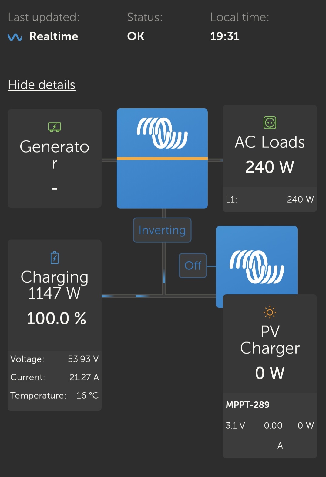
The SSH command allowed me to successfully change the AC input. I was hoping it would capture the wattage coming in from the rectifier as it will be coming in from a generator or the mains. It shows up as an 1147W supply on the battery instead but I suppose as far as the GX is confirmed its just a DC power supply.

1000011238.jpg

Since this test did not work I can't seem to think of another reason to activate the AC input feature?

0 Likes 0 ·
1000011238.jpg (157.2 KiB)
mr-manuel avatar image mr-manuel northtown2022 commented ·
Probably it would be better if you open a new question for this.
1 Like 1 ·