Hi,
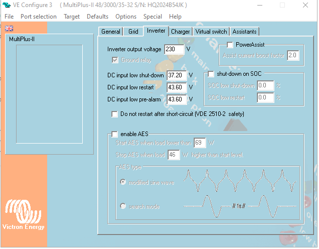
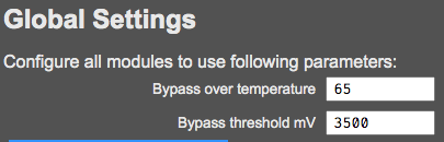
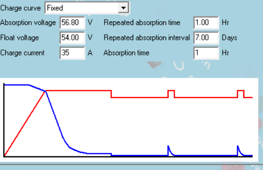
Here are my settings :

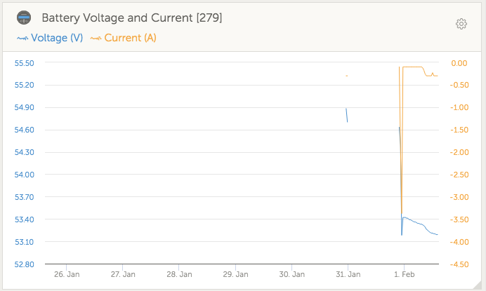
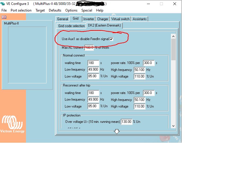
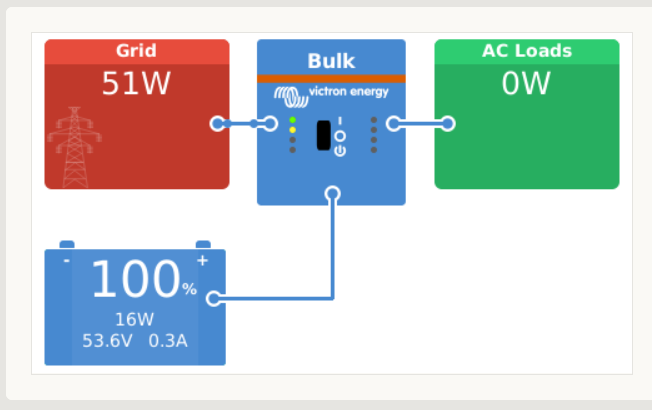
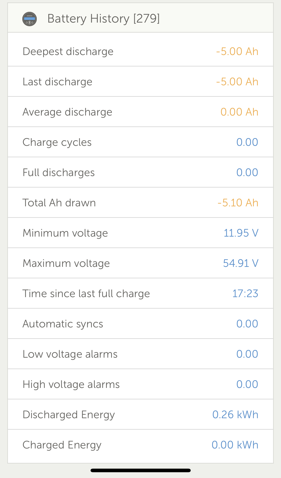
the voltage is atm 53V and the Multi states low battery BUT it's in Inverting mode which i don't understand. First the battery is not low and from what i can tell i have set the switch correct from the BMS so right now the Aux 1 is Open but never the less the Multi states low battery and more bizarre it is in Inverting mode whereas if it was really low battery then it should be in Charge only mode. I don't understand. Could somebody explain what am i missing ?
/peter
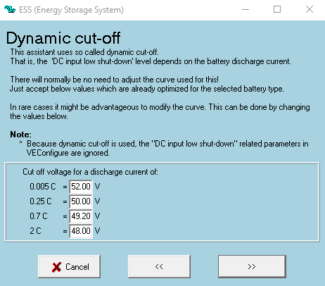


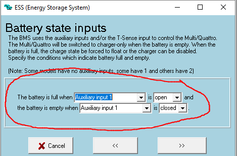
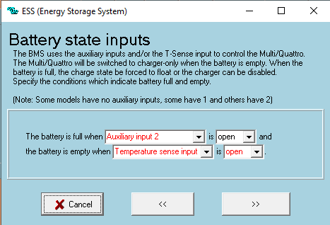


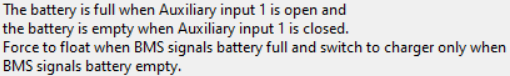
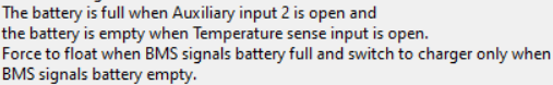
 and the relay on Aux 1 is On in the BMS meaning it's Open circuit eg. means the battery is full but the charging specs in VE Config says this :


