question

pmikep avatar image
pmikep asked

AC OUT showing some power even in Charger Only mode

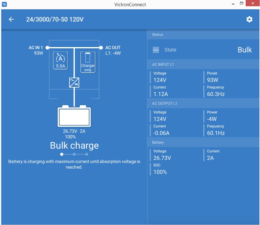
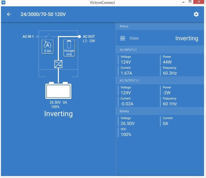
A small nit. Am running v476 on a MultiPlus 24/3000/70. Charger Only mode. Nevertheless, AC OUT is showing anywhere from 1 to 18 W, variable. I don't have anything hooked up to the AC terminals. Seems to show more power the more current the charger sends to the batteries.

I assume noise?

Even so, shouldn't the software force "0 W" on AC OUT when in Charger Only mode?

MultiPlus Quattro Inverter Charger
2 |3000

Up to 8 attachments (including images) can be used with a maximum of 190.8 MiB each and 286.6 MiB total.

2 Answers
Alexandra avatar image
Alexandra answered ·

@pmikep

While the inverter is not inverting there are element in the system that use power. The GX device uses power so does the mppt.

So the power useage you are seeing are not your loads it is the system load or self consumption.

2 |3000

Up to 8 attachments (including images) can be used with a maximum of 190.8 MiB each and 286.6 MiB total.

pmikep avatar image
pmikep answered ·

@Alexandra Thanks for replying. But, no, this is not self-consumption.

Here is a screen shot that shows the AC Out (L1) making -4 (that's "minus four) Watts in "Charger only' mode.

multiplus-noise.jpg


If I posted a video, it would show the AC Output wandering up and down from a few Watts positive to a few Watts negative.

I do not have a load connected to the AC Out terminals. That is, the AC Out terminals are "floating," open circuit.

Clearly, an open circuited terminal cannot flow a sustained current (here showing -0.06 A) nor generate power (-4 W). (And note too, that 124 V multiplied by -0.06 A does NOT equal -4 W. It equals -7 W. So the power calculation isn't even correct in this situation.)

If I connect a load to the terminals - even though I am in 'Charger only' mode and the load is not being powered by the Multiplus, then the AC Out stays at a steady 0 W.

So this wandering appears to be noise (EMI, perhaps from the Multiplus itself in Charging mode) on the terminals of the AC Out connector.

Which leads me to hypothesize that there are no "pull up" or "pull down" resistors on the AC Out terminals. (Or no resistor across Line and Neutral to zero out any offset voltage between them caused by rectifying RF.)

Perhaps the engineers at Victron thought that every MultiPlus would have a load connected to AC Out. ('Cause, otherwise, not using AC Out makes the MultiPlus a really expensive (but very customizable) Battery Charger.) But I can see cases where users might use it at a Battery Charger only. (Perhaps they're using another inverter - which is what I was doing here.)

Anyway, Best Practice for terminals that face the outside world is to use resistors (10K-ish) to either "pull up" or "pull down" (to ground) any noise voltage on the terminals. Or a resistor across terminals to zero out offset voltage between terminals.

Since changing PCB design for such a corner case is probably not worth the trouble, and since it's more of an oddity than anything else that the UI shows anything other than 0 W on AC Out when in 'Charger only' mode, I'm back to my original suggestion that the software simply force the UI to show "0 W" on AC Output L1 whenever the MultiPlus is in "Charge only" mode.


2 |3000

Up to 8 attachments (including images) can be used with a maximum of 190.8 MiB each and 286.6 MiB total.