question

hummingbear avatar image
hummingbear asked

Multiplus AC Loads jump when Generator/AC Input is provided

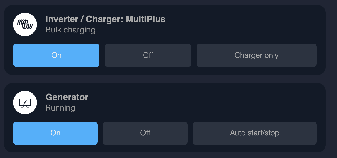
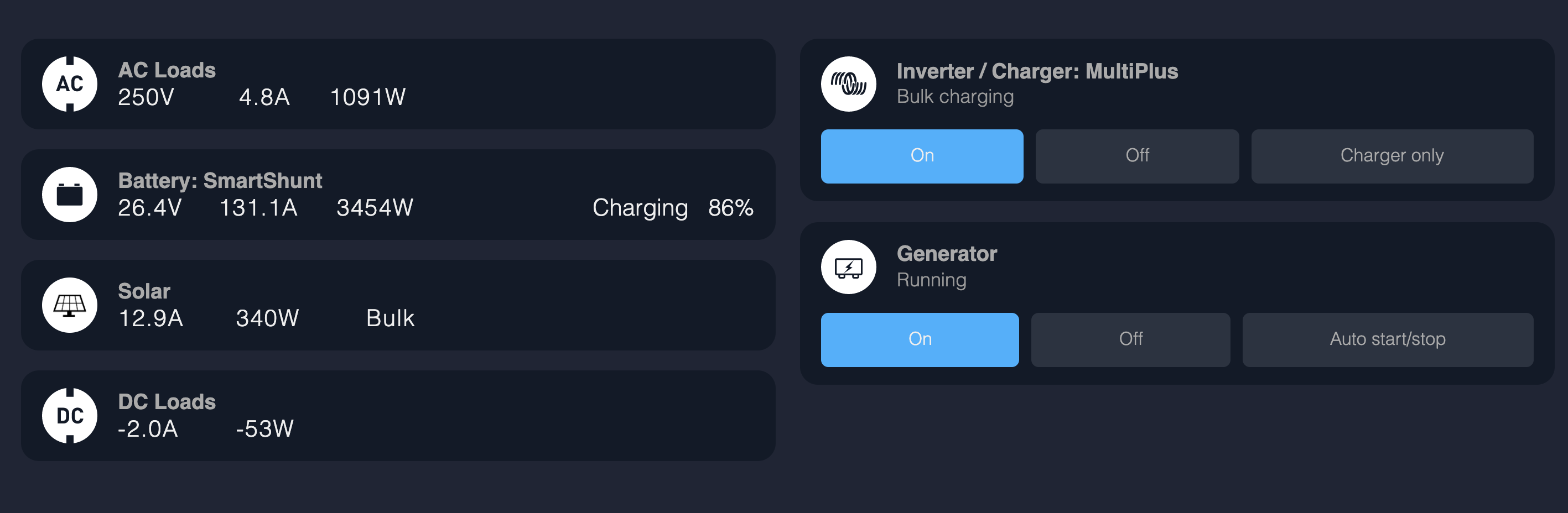
I have a Multiplus 230V 5000VA that uses my Generator as AC1 Input. I occasionally use my generator to charge my batteries when we get a string of cloudy days. I follow my AC loads quite closely and I notice that when the multiplus accepts AC1 Input, then AC loads shoot up about ~700-1000W


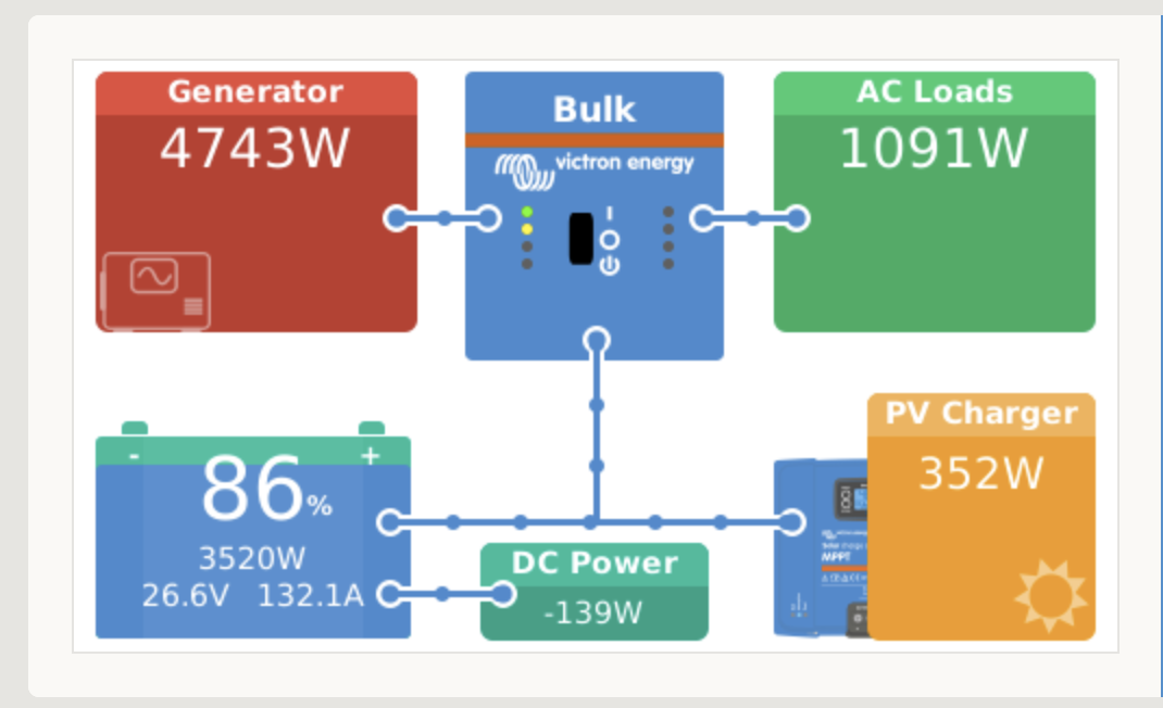
Is there something I'm missing? Is the multiplus using extra AC power to charge my batteries? I separately am able to see the generator power going to the batteries. See screenshot below, generally I am not using more that 400W on AC right now
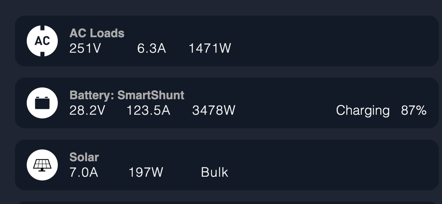
1608227549986.png

1608227580161.png

MultiPlus Quattro Inverter Charger
1608227549986.png (67.5 KiB)
1608227580161.png (64.7 KiB)
2 |3000

Up to 8 attachments (including images) can be used with a maximum of 190.8 MiB each and 286.6 MiB total.

3 Answers
deverm avatar image
deverm answered ·

I had similar behavior today, it was caused by my ground jumper to the neutral output of the auto transformer. In my case, it created enough bias for my galvanic isolator to trigger (I have another shore power with isolation transformer that does not show this problem)

in your case I suspect that you have connected L1 and L2 of the generator to L and N of the Multiplus and did not connect the generator N but have grounded that N?

you must remove ground from all generator output coils.


10 comments
2 |3000

Up to 8 attachments (including images) can be used with a maximum of 190.8 MiB each and 286.6 MiB total.

hummingbear avatar image hummingbear commented ·

@DeVerm I am just seeing your post. Yes I believe the generator ground is connected to the neutral. And you are correct that `L1 and L2 of the generator to L and N of the Multiplus`.


When I initially setup my generator input to Multiplus I poked around to see where the ground was bonded on the generator but it was not immediately apparent so I let it be.


Do you know why this would cause the AC usage to jump though?

0 Likes 0 ·
deverm avatar image deverm hummingbear commented ·

Yes, the genset N is like a center tap between L1 and L2 just like the auto transformer. When both are bonded to ground, they are connected and windings put in parallel. A small difference in ratio causes current to flow through neutral.

0 Likes 0 ·
hummingbear avatar image hummingbear deverm commented ·

Is this extra 1000W that's showing up essentially energy that's being thrown away? I mostly grasp what you're describing (and understand I need to remove the genset ground to neutral bond) but I don't get where the energy is going?

0 Likes 0 ·
deverm avatar image deverm hummingbear commented ·

you want all power from the generator to go via L1 and L2. But by grounding N, power, for example, also flow from genset L1 through its windings to genset N, then gets out via ground, travels to the N of the auto transformer, through its winding to L2 back to the genset. It’s heating up the windings.

0 Likes 0 ·
hummingbear avatar image hummingbear deverm commented ·

Thanks for taking the time to respond, much appreciated. I'm going to try and un-bond the ground tomorrow and test it out.


By windings do you mean wires/connections? I've felt the wires going to/from the inverter and multiplus after running the generator and they aren't even the slightest bit warm. I'd expect 1000W to be palpable but maybe there's enough wiring that it dissipates itself?


In either case that doesn't sound good and hopefully I'll resolve it soon.

0 Likes 0 ·
deverm avatar image deverm hummingbear commented ·

It’s the windings of the transformer and the coils in the generator. Outside, the current runs through the ground wire between generator and auto transformer.

glad to see you fixed it!

0 Likes 0 ·
hummingbear avatar image hummingbear deverm commented ·

So how can I buy you a coffee? That was definitely the issue, you nailed it. I'm really glad it didn't cause any other problems. I'm way out here off-grid and it's hard to get an electrician here so I often have to become my own.

Nonetheless I'm going to bite the bullet and get someone out here to inspect all my work. I don't like that this happened but I'm glad we found the problem.

0 Likes 0 ·
Sean Jacobs avatar image Sean Jacobs commented ·
So I'm experiencing something similar when my grid connection comes on when battery voltage gets too low. I'm guessing I have a neutral/ground bond somewhere I shouldn't.... like in the all the panels. I need to unbond ALL grounds from neutral outside of autotransformer? That's my understanding.


I have the ground relay wire from autotransformer to quattro and ground relay turned off in quattro. As per wiring diagrams.


I'm going to have to go back and do some serious probing about.

0 Likes 0 ·
stevesea avatar image stevesea Sean Jacobs commented ·
Could you figure it out? I'm having the same problem when grid comes online (I have a multiplus and autotransformer, both connected following the diagram for split phase supply for unbalanced load). The issue is that grid neutral is always going to be bonded to ground (at the service entrance and/or at the pole).
0 Likes 0 ·
stevesea avatar image stevesea Sean Jacobs commented ·

I was able to track down my problem to a autotransformer (AT) neutral to grid neutral loop. My installation is in a old house, and there seemed to be a neutral circuit in a panel serviced by the autotransformer that was bonded to the neutral from grid side, and because the grid neutral is "different" than the AT neutral, it has a voltage and thus a current if bonded. I was able to track it down by turning off all breakers serviced by the AT, and disconnected the L1 and L2 outputs of the AT (and in this condition, I still had a load because it was flowing via the AT output neutral). Then using a amp meter I was able to locate the neutral circuit looping back to the grid and disconnected it. This corrected the loads while connected to grid, and confirmed it by turning off all loads serviced by the AT, and making sure the load went down to zero (sometimes said 1-6 W but I'll call it close enough for government work). After disconnecting that neutral I expected to have some plugs or lights to not turn on but surprisingly I didn't find any at first search. Maybe it's because I've not found it, or maybe it's because it's using the grid's neutral. This is an old house and renovated a few times so there's a little of uncertainty on the wiring... so some extensive exploration is required to correctly map all circuits. But at least the loads are good now and no loops seem to exist anymore.


Edit: While writing this I realized another check I have to do now, I have to check that no electricity is actually flowing back to the grid side in the event of a power outage via the circuits serviced by the AT (since again, this is an old house and it appears people did some questionable wiring on the circuits, so I have to confirm that the circuits don't loop back to the grid side).

0 Likes 0 ·
Paul B avatar image
Paul B answered ·

I notice that the AC voltage is 251 volts, suspect that when you are inverting that the voltage is around 230 volts and then when the gen connects the generator is out puting 251volts, this may well be the reason.

solution adjust your generator down to 230 volts as 251 is really a little bit high

2 comments
2 |3000

Up to 8 attachments (including images) can be used with a maximum of 190.8 MiB each and 286.6 MiB total.

hummingbear avatar image hummingbear commented ·

The inverter is set to 240V, and the Gen puts out ~250V. I'm not sure I can adjust this.

I don't understand how that would cause a spike of 1000W, can you explain that bit?

0 Likes 0 ·
Paul B avatar image Paul B hummingbear commented ·

How about doing a VE Configure screen shot while on inverter only and then with the same loads running another screen shot of VE config screen. also if you have a Power factor meter then please also measure this when on inverter only and again when using the generator.

Also check the AC1 out amps on inverter only with a Clamp meter and again when you have the generator running

I would say the Multi is reading correctly, as the watts is just amps x volts. but as to why you have the jump in watts when running the generator is the question.

so to be clear we need these readings

While on inverter only

1. Voltage output

2. Amps Output

3. Hz figure

4. Power factor


Then the same again with the generator running. WITH THE EXACT SAME LOADS.

also do the above with the battery charger amps set to ZERO (use VE config to set this) or just untick enable charger which ever one is fine

then report again with the charge amps set to your normal level.

The more info you can provide the more chance we have of pointing whats causing it for you.


Keep in mind that when you have the generator running then its a direct pass through and as long as the amps and volts readings are correct then the figures you are seeing are the real figures from your generator.

NOTE DO you have anything connected to AC2 out on the multiplus as this only turns on when a generator is connected. maybe you connected a water heater to AC2 OUT ?????? just a thought ?????

0 Likes 0 ·
JohnC avatar image
JohnC answered ·

Hi @hummingbear

Are you perchance using the 'WeakAC' setting in the Multi to enable generator acceptance? This fools with power factor and might explain it.

Maybe next time you run the genny you could post up a screenshot showing a power balance over the Multi - say the GX home screen or VRM Dashboard. Plus the dc A and V into the battery..

4 comments
2 |3000

Up to 8 attachments (including images) can be used with a maximum of 190.8 MiB each and 286.6 MiB total.

hummingbear avatar image hummingbear commented ·

Hey John - WeakAC setting is disabled. Took a screenshot of my charger settings from VEConfig. I also fired up the generator and took a few screenshots below. Any help/diagnostics appreciated


1608397399139.png

1608397420469.png

1608397426787.png

0 Likes 0 ·
1608397399139.png (975.1 KiB)
1608397420469.png (167.3 KiB)
1608397426787.png (153.0 KiB)
JohnC avatar image JohnC ♦ hummingbear commented ·

@hummingbear

Just a coupla little things..

60 Hz? Is this right? What happens to that when the genny is on?

The negative DC Power indicates a charge situation. Is that happening, or do you actually have dc loads at the time? This is a calculated figure, and might be indicating one (or more) of the sources is unreliable. And of course these things are sampled at different times, leading to variability. So often hard to pin down, but there should be a 'leaning' there. Does that -ve look realistic?

Your Multi is capable of 120A charge, yet you show >130A. I can't test this myself, but I wouldn't expect this to be possible consistently.

Just searching for clues..

0 Likes 0 ·
hummingbear avatar image hummingbear JohnC ♦ commented ·

@JohnC thanks for taking the time to look into this, some of my answers to your questions below:


60 Hz? Is this right? What happens to that when the genny is on?
Yes, I'm in the US so 60Hz. I should also explain my setup a bit more. I have a 240V Multiplus that goes to an Autotransformer and is splits into two 120V Legs. But yes we are 60Hz here


The negative DC Power indicates a charge situation. Is that happening, or do you actually have dc loads at the time? This is a calculated figure, and might be indicating one (or more) of the sources is unreliable. And of course these things are sampled at different times, leading to variability. So often hard to pin down, but there should be a 'leaning' there. Does that -ve look realistic?
I do have DC loads, but they are in the 10-30W range. 130W seems high but maybe this is the Multiplus with fans running, I would assume what the multiplus uses for fans is pulled as DC?


Your Multi is capable of 120A charge, yet you show >130A
That extra is from the PV Solar Charger. I have my Venus set to allow a total of 150A to the batteries.

------

I'm still perplexed as to why my AC loads go up to 1000W+. Right before the generator turned on my house was pulling AC loads in the range of ~150-350W. I agree that there is some variability in the calculations, but AC loads jumping 800W+ seems does not seem like normal variability. I'm sure there's an explanation but I have no idea what it is yet

0 Likes 0 ·
JohnC avatar image JohnC ♦ hummingbear commented ·

@hummingbear

The '800W' isn't really normal, but I have seen suchlike when power factor comes into it.

Now I know little of the US splitphase (and don't want to learn), but that does make me wonder what that downstream autotransformer is up to, and what effect it's having??

That's where I'd be looking. Other than that, I think I'm done..

0 Likes 0 ·