question

pmano avatar image
pmano asked

Need help with CLS500 placement, grounding issue, Battleborn batteries tech team?

Greetings,


I have an issue with the advice I was given for the placement of the CSL500 ( Current Surge Limiter ). Instructions - These were 1 page printed shipped with it.

From bottom of page:
'Note: Either the negative battery terminal OR the negative DC input to the inverter/charger should be connected to an earth or chassis ground. NOT BOTH! Connecting both to ground will bypass the device.'


* Interesting, the instructions shipped do not match the BB sites

https://1t1pye1e13di20waq11old70-wpengine.netdna-ssl.com/wp-content/uploads/2019/01/Current-Surge-Limiter-Quick-Guide-CSL-r03.pdf

- The INV- Terminal is connected to the Inverter/Charger Negative Terminal.
- The Bat- Terminal is connected to the Battery Bank Negative Terminal.
- The INV+ Terminal is connected to the positive Terminal of the Inverter/Charger.
- The Battery Bank Positive Terminal is connected to the Inverter/Charger Positive Terminal.
- The Battery Bank Negative Terminal is connected to ground.
- The Inverter/Charger Negative Terminal is NOT CONNECTED to Ground.


'Negative DC terminal' - they do not specifically say 'chassis or earth ground'....


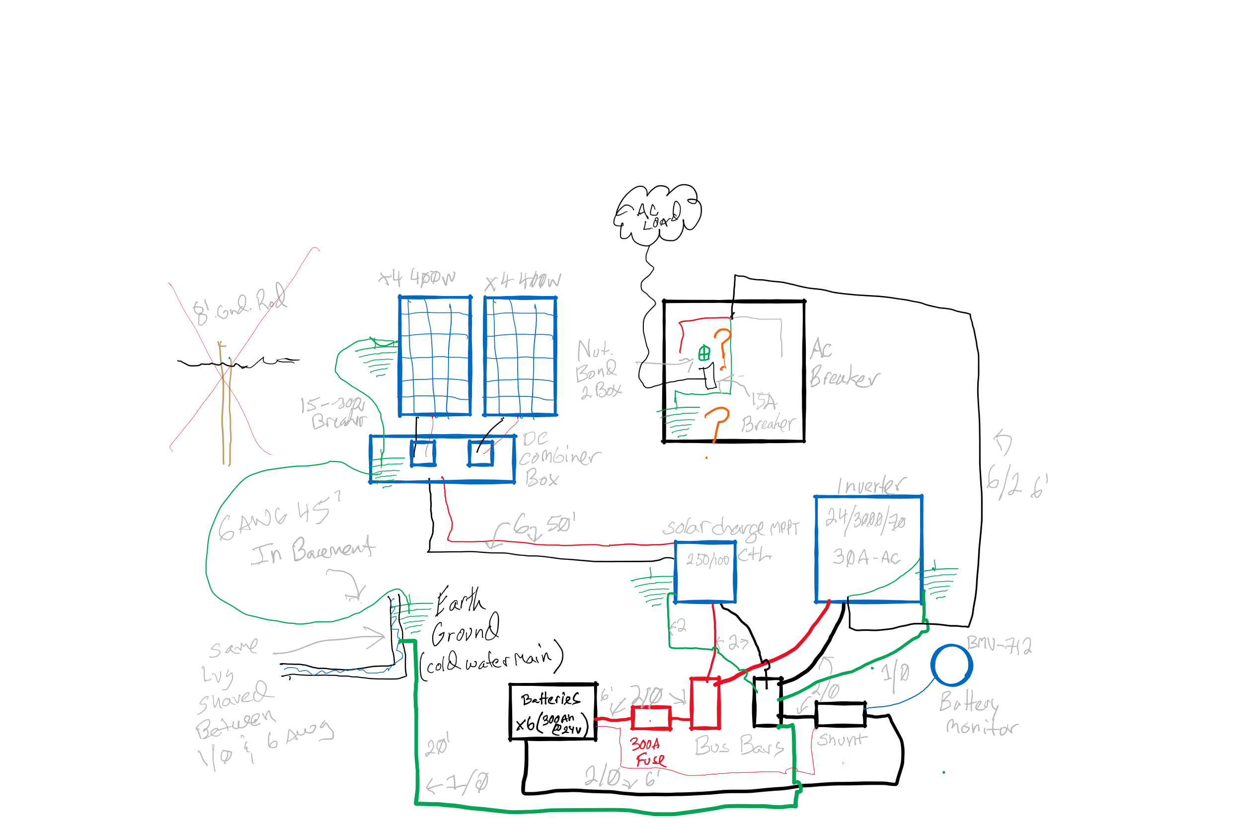
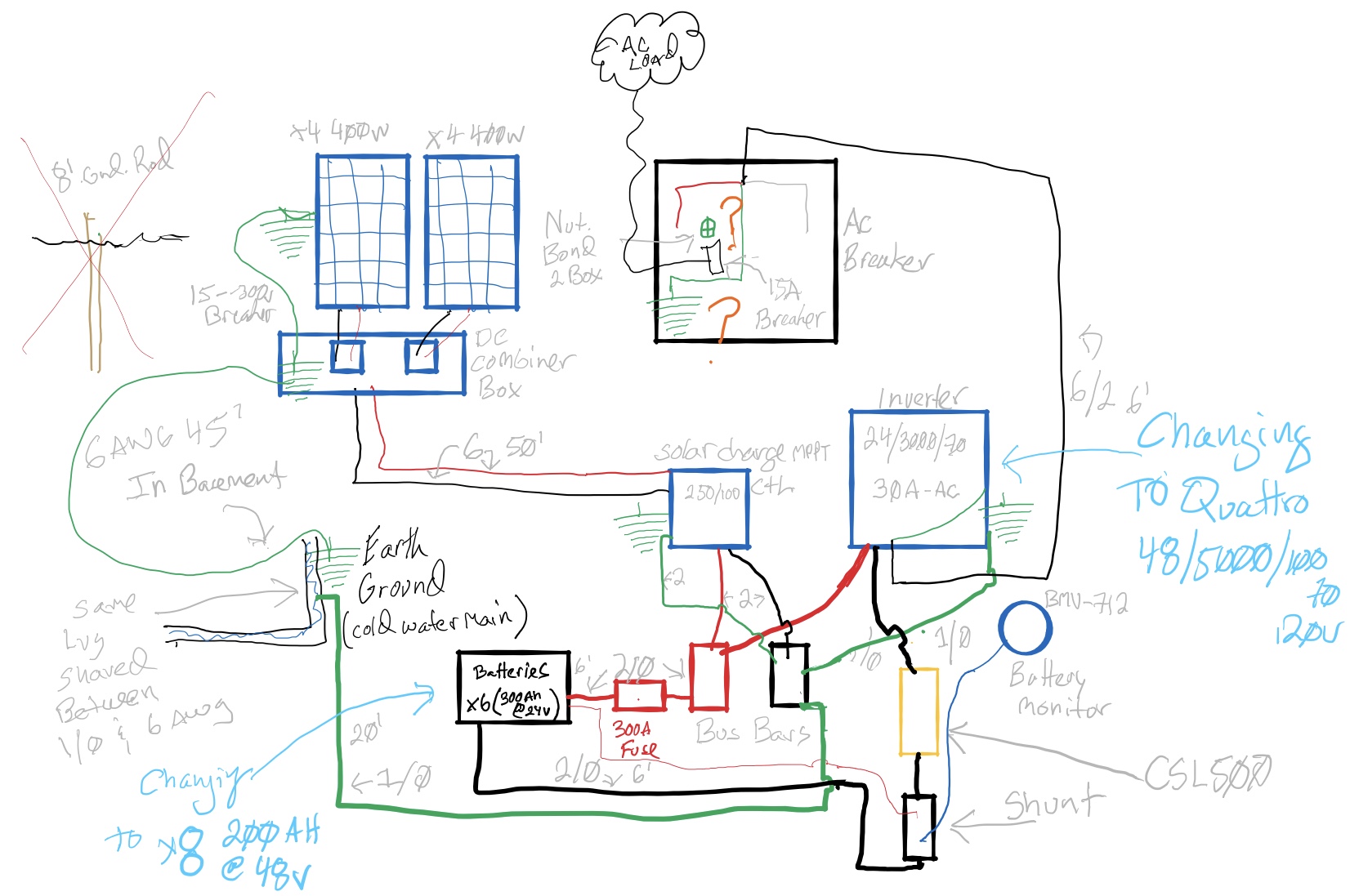
Two wire diagrams, Current and future, the Gold rectangle is the CSL500.

I was told to put it between the SHUNT and he Inverter -.

This is an issue for the Charge controller - to - Battery bank circuit, if I am not mistaken, since input current negative will have to pass through the ground on the common negative bus bar and up into the ground of the inverter, to complete circut with the battery bank?


Would the correct way to deploy this be to connect both the Inverter - and Chassis Earth ground to the negative side of the CSL500 and the battery - ( from the common - bus bar? )


Thank you for your time in advance.


( also, is the Multiplus 24/3000/70 or Quattro 48/5000/100 - 70 120v have its internal neutral bonded to chassis ?)


MPPT ControllersMultiPlus Quattro Inverter ChargerGrounding
future-cfg.jpeg (320.1 KiB)
current-cfg.png (465.8 KiB)
1603920506210.png (7.0 KiB)
2 |3000

Up to 8 attachments (including images) can be used with a maximum of 190.8 MiB each and 286.6 MiB total.

1 Answer
owenfi avatar image
owenfi answered ·

I found this because I have much the same question. Did you ever migrate from the 'current' diagram, to the 'future'? (Also I wasn't able to see the 3rd attachment)


I don't believe it will work because there isn't a path from your solar mppt/negative bus bar back to the battery. I think you should keep the connection from the negative bus bar to the shunt, and then on to the battery. My suggestion would be to go from negative terminal of inverter via the CSL500 to the negative bus bar. The negative bus bar would be tied to ground, but also continue via the shunt to the battery negative terminal.


However, that doesn't answer whether to plug the chassis ground via the CSL 500. I'm leaning towards connecting it that way, but I don't feel good about it.


Here is why:


The Quattro 5000 Manual in section 4.5 Connecting AC Cables, states:

  1. The Quattro is provided with a ground relay (see fig 1)) that automatically connects the N output to the casing if no external AC supply is available. If an external AC supply is provided, the ground relay H will open before the input safety relay closes (relay R1 or R2).

What that means is, during off grid operation (what it seems like is your case, and is my case most of the time, since I'll be adding it to an RV with shore power) the N output is connected to the case/chassis ground connection point.


So, if the chassis-ground connection of the Quattro was connected to the system ground/chassis then it would allow a path to bypass the CSL500 (and potentially carry too much current if the CSL500 fails or is removed).


However, NEC requires that: "the removal of any device cannot interrupt the ground path"

https://ohsonline.com/Articles/2003/11/Preventing-Shock-with-Proper-Grounding-Techniques.aspx


It sure seems like the CSL500, if all negative/ground/chassis wires are going via it to the negative bus bar to the ground would be violating that requirement (hence why I don't feel good about it).


So, I think the answer is to connect the Chassis Earth to the INV- on the CSL500, but I'd be curious what you ultimately ended up doing if you have solved this problem. Or if anyone else can weigh in with thoughts.


Update: I heard from Battleborn that ”The case ground(not the internal ground point) on the quattro can be connected to the chassis”


So that seems better to me! Furthermore I now realize the “N Output” in the Victron docs refers to the Neutral (and the output!) so don’t believe there is risk of second path issue as described above.

2 |3000

Up to 8 attachments (including images) can be used with a maximum of 190.8 MiB each and 286.6 MiB total.