question

Christopher A avatar image
Christopher A asked

Am I seeing the correct numbers?

I have 1200 watts of solar on my RV roof and a Smart Solar MPPT 150/70 controller. Right now, I have all the panels in series and the controller sees a volatage of 147V from the PV. This is correct. When I enable the controller to charge the battery, the voltage drops to 98V and current shows 2.2 amps in good sun while the solar shows 218Watts. I have two 6V agm batteries in series. I also have a BMV 712 and those number also make sense, although I'm not 100%.

Questions are:

1. Am supposed to see a number closer to the Wattage of my PV array (1200Watts)?

2. When charging in Bulk Stage, the blue LED blinks every 3 seconds although voltage shows 99+ Volts.

3. When the charger switches to Absorption, the amber LED blinks every three seconds.

If something is suspected wrong, what steps can be taken to troubleshoot it? I am pretty technical but don't know where to start as I'm not sure what readings I am supposed to be seeing and if the ones I'm seeing are correct or way off.


Thank you.


MPPT Controllers
2 |3000

Up to 8 attachments (including images) can be used with a maximum of 190.8 MiB each and 286.6 MiB total.

14 Answers
Christopher A avatar image
Christopher A answered ·

Ok, Well Markus makes sense, Thank you. I need to increase my battery capacity.

My question arises from what the app shows as far as what is shows being correct or what is it supposed to show. This is what I cannot figure out, besides using math.

AND

Why does the MPPT charger have the bulk and absorption light blinking every three seconds during full sunlight, voltage and showing power production? According to the manual, this indicates an error.

2 comments
2 |3000

Up to 8 attachments (including images) can be used with a maximum of 190.8 MiB each and 286.6 MiB total.

irwinr avatar image irwinr commented ·

You're right: The manual indicates that bulk and absorption blinking indicates "Internal error" which includes: "current sensor issue"

You should contact Victron Support. It's possible when you had your 4 panels in series and were pushing 150v that you may have damaged the MPPT unit. If there is an internal error such as a current sensor issue then that means the numbers reported in the app could very well be incorrect.

0 Likes 0 ·
Christopher A avatar image Christopher A irwinr commented ·

During Bulk charge mode the LED Blinks once every three seconds. No other LED blinks.


During Absorption stage the LED blinks once every three seconds. No other LED blinks.


The two lights do not blink simultaneously..


The manual says:

"Note (*1): The bulk LED will blink briefly every 3 seconds when the system is powered but there is insufficient power to start charging."

This cannot be happening as the above statement says as there is plenty of power to start charging and it is charging. Is the book in error and it always blinks once every three seconds or am I looking at a different issue?


Also, it never got to 150 volts and the panels were in series was briefly as a test scenario. The specifications also state if more power is connected, the controller will limit power, I assume without damage, but again, power was always within it's specifications.

0 Likes 0 ·
Guy Stewart (Victron Community Manager) avatar image
Guy Stewart (Victron Community Manager) answered ·

4 x 60 cell panels (147V) in series is WAY TOO CLOSE to the strict 150V limit which will damage the charge controller. It can go over 150V in cold weather.

If you have 4 panels, you need to reconfigure them to be in 2 series and 2 parallel. Configure your panels using this MPPT sizing calculator to help with the correct configuration:

https://www.victronenergy.com/solar-charge-controllers

1 comment
2 |3000

Up to 8 attachments (including images) can be used with a maximum of 190.8 MiB each and 286.6 MiB total.

Christopher A avatar image Christopher A commented ·

A day ago I had the panels in 2 + 2 series and parallel to not get to the charger limit. I put them in series for one day to see if things with the numbers changed or made sense. Only the voltage changed (as it would). I have now switched them back from Series to 2 + 2 series and parallel and still get the blinking blue and amber lights every three seconds. HOW DO I FIND IF THERE IS A PROBLEM? There is nothing to reference as to what I should be getting and all the documentation is lacking any real troubleshooting or expectations on what the chargers should yield.

0 Likes 0 ·
markus avatar image
markus answered ·

How much Power comes from your panels depends on how much power is used. Where do you expect the Watts to go to? If you simply charge your (small) battery without additional loads, you will never see full power of your charger.

Regards,

Markus

2 |3000

Up to 8 attachments (including images) can be used with a maximum of 190.8 MiB each and 286.6 MiB total.

irwinr avatar image
irwinr answered ·

Have you verified nothing is shading any of the panels? In good sun you should definitely be seeing more than 218 watts from a 1200 watt array. That's only 18% of your capacity. Even at winter solstice with the panels completely flat on a horizontal roof you should be able to hit 60% of the arrays capacity in good sun. When my panels were new I was exceeding 100% of their rated power the first few months I had them on good clear days.


The fact that the voltage drops from 147 down to 99 from only 2.2 amps of current implies there's a significant voltage drop across a panel somewhere. What kind of panels are they? Do they have bypass diodes installed? Are you sure no part of any panel is shaded by anything on your roof?


You might want to test each panel individually. Most multimeters can handle up to 10 amps of current. This makes it very easy to test two aspects of each individual panel: Voc (Voltage Open Circuit) and Isc (Current Short Circuit). These numbers should be published by your panel manufacturer. It sounds like you have four 36 volt panels at 300 watts each? If so each panel should have a max current rating of around 8 amps or so.


Keep in mind you won't achieve 100% of the published numbers unless you're in an ideal configuration, such as perfectly clear sky, summer solstice at high solar noon and the perfect angle for your latitude. That said: Voc should come very close and Isc should be at least 60-70% of the published figure in good strong sun.


3 comments
2 |3000

Up to 8 attachments (including images) can be used with a maximum of 190.8 MiB each and 286.6 MiB total.

Christopher A avatar image Christopher A commented ·


I have checked the output of each panel in full sun (Almost always sunny here in the desert) and I get the numbers I probably should. 36V and around 6 amps each panel in winter with the panel flat to the ground. Max current published is 9 amps Isc on these panels.

My question arises from what the app shows as far as what is shows being correct or what is it supposed to show. This is what I cannot figure out, besides using math. All the numbers I'm questioning are those shown on the app. The image is of 1200 watts of panels with 2 + 2 series/parallel. Measurment at the input to the charger with no load is about 74 Volts. Pretty much exactly where it should be. The app shows different numbers but there is the battery load. This is where I am confused.

0 Likes 0 ·
img-5535.jpg (67.4 KiB)
irwinr avatar image irwinr Christopher A commented ·

It's normal for the voltage to drop when you apply a load. The 74 volts is "open circuit" voltage but the typical Vmp (Voltage at max power) of that size panel would be around 60 volts. Therefore under load you should see voltages closer to 60v.

Based on the numbers shown in that screenshot you don't appear to be load constrained. If the batteries were close to full the bulk charge voltage should be closer to 14.4 - 14.6v. The fact that it's in bulk and only at 13.65v means the batteries should be able to take much more charging current. Also if you were load constrained your input voltage from the panels should be closer to 60v+.


What do you have your bulk charging voltage set to?


To me, when I see that big of a voltage drop on the panels at such a small level of current it implies:


1.) Shading on one of the panels.

2.) Resistance somewhere in the wiring. This could be a bad connection, undersized wiring, etc. (See page 5 of the SmartSolar manual)


0 Likes 0 ·
Christopher A avatar image Christopher A irwinr commented ·

I really doubt it's a resistance problem, As I'm a low voltage specialist and know my way around constructing cables and fittings Plus it's oversized for such a relatively small system for an RV. None-the-Less, I will troubleshoot the wiring.

It's the flashing Bulk LED that is bothering me the most. The manual says:

"Note (*1): The bulk LED will blink briefly every 3 seconds when the system is powered but there is insufficient power to start charging."

and @ 51+ Volts, that is plenty to start charging. And the numbers show charging and current being delivered to the batteries.

0 Likes 0 ·
wkirby avatar image
wkirby answered ·

The bulk and absorb LEDs flashing is of some concern to me. It susggests either the factory calibration settings are lost (bad) or that the current sensor has an issue (also bad). Any of the aforementioned issues would cause erroneous readings.

1 comment
2 |3000

Up to 8 attachments (including images) can be used with a maximum of 190.8 MiB each and 286.6 MiB total.

Christopher A avatar image Christopher A commented ·

Is there anyway to troubleshoot the issue besides a trip to The Netherlands? There is not much documentation on this or ways to support finding of a bad sensor. I called the company I purchased it from, and they don't really offer support.

0 Likes 0 ·
Christopher A avatar image
Christopher A answered ·

I don't know of any way to troubleshoot the blinking LEDs on the MPPT. As far as I can tell, it's installed correctly and very simply. Panels to controller to shunt(-) to batteries. There is no documentation on troubleshooting the controller. Anybody have ideas?

2 comments
2 |3000

Up to 8 attachments (including images) can be used with a maximum of 190.8 MiB each and 286.6 MiB total.

solarone avatar image solarone commented ·

@dishusa You could try the Victron toolkit app it gives you examples of what the leds are doing

0 Likes 0 ·
Christopher A avatar image Christopher A solarone commented ·

The app is generic on what it should be doing. The book says "

Note (*1): The bulk LED will blink briefly every 3 seconds when the system is powered but there is insufficient power to start charging.

But it is charging. This is what is bothering me.

0 Likes 0 ·
Christopher A avatar image
Christopher A answered ·

After more and extensive troubleshooting, this is what I currently have come up with.

The MPPT 150/70 seems to be working correctly. The blinking Blue Bulk LED was the issue when it is in charging state and it appears there is NO reason for it to blink. As the manual says:

"Note (*1): The bulk LED will blink briefly every 3 seconds when the system is powered but there is insufficient power to start charging."

Here is what I found. When networked to the BMV 712, the MPPT will blink the bulk LED every three seconds when in bulk charge mode. All the numbers look correct, though and it should not blink.

When the BVM 712 is disconnected from the network, via the app, the blinking stops AFTER a reboot of the MPPT (kill all power to it, wait three minutes, power back up).


As for WHY? I have no clue. I did not make this stuff, but all the hookup is absolutely correct and the voltages and numbers are where they should be. No panel shorts, sun outages, shading, incorrect cable sizing, distances, poor connections, voodoo, sun eclipses, nuclear fallout, acts of God or anything else appears wrong.


2 |3000

Up to 8 attachments (including images) can be used with a maximum of 190.8 MiB each and 286.6 MiB total.

Paul B avatar image
Paul B answered ·

Just a question, when you say networking - how have you connected the Mppt unit to the BMV unit that you mention.

the only way the mppt should have any connection to the BMV is via the Shunt and the neg and Pos Battery connections.

also could you screen shot the settings page under the battery selection

1 comment
2 |3000

Up to 8 attachments (including images) can be used with a maximum of 190.8 MiB each and 286.6 MiB total.

Christopher A avatar image Christopher A commented ·

The mppt is connected to the BMV via Victron Connect. The MPPT output battery negative is connected to the - on the shunt where it says "charger". The + is connected directly to the battery bank via a 80A breaker. This is a simple configuration and correct.

0 Likes 0 ·
Paul B avatar image
Paul B answered ·

Also a few shots of the history page as well please

2 |3000

Up to 8 attachments (including images) can be used with a maximum of 190.8 MiB each and 286.6 MiB total.

Christopher A avatar image
Christopher A answered ·

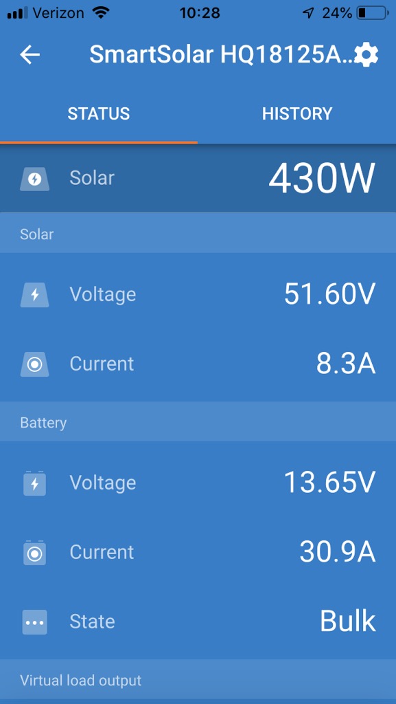
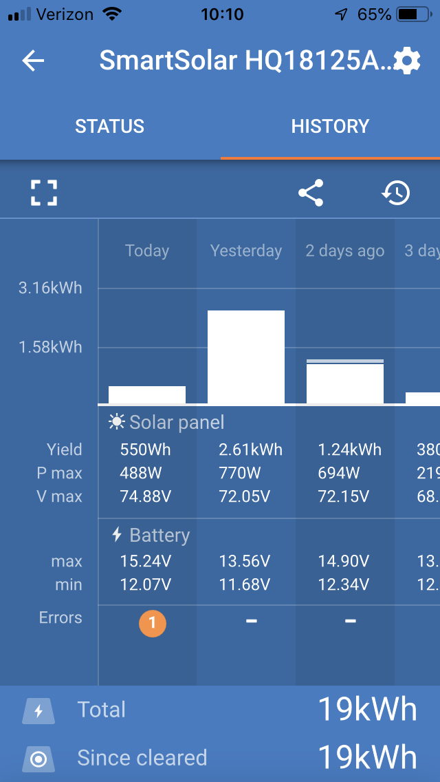
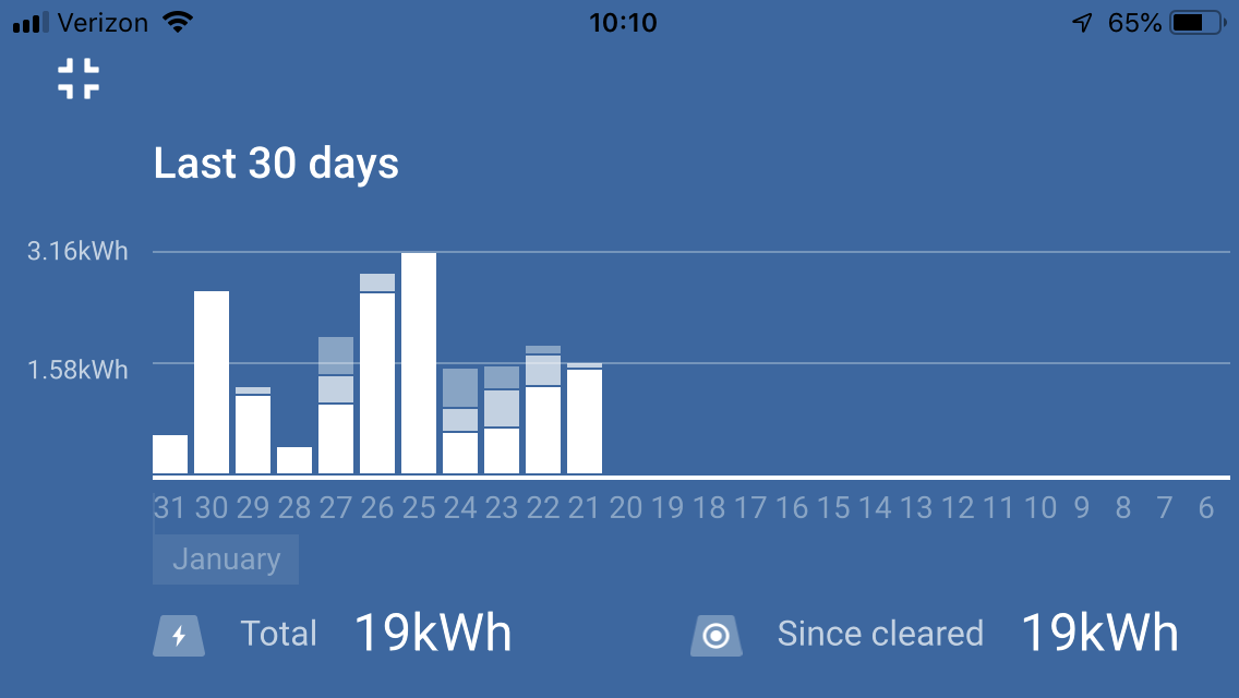
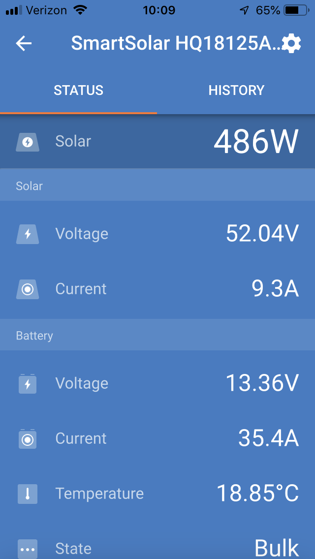
Here are the screen shots today in 32 degrees Latitude, full sun, southern exposure, no shading, panels mounted flat. 4 panels 2 + 2 parallel / series. Each panels is 300W, 37 VOC, 9A ISC. Tested each panels individually this morning with no load. Each panel performs as the specifications show. Tested them in series and and parallel configuration. Numbers are exactly right on to where they should be due to time of day and angle to sun. 74.3V and 7.68A Input to the charger with no load.
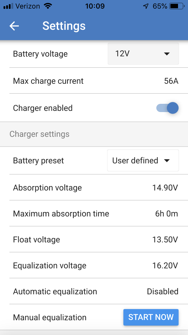

img-5552.png (133.9 KiB)
img-5553.png (125.3 KiB)
img-5554.png (97.8 KiB)
img-5555.png (162.9 KiB)
2 |3000

Up to 8 attachments (including images) can be used with a maximum of 190.8 MiB each and 286.6 MiB total.

Christopher A avatar image
Christopher A answered ·

The error in the one pic of the history was me shutting it down via the breaker.

2 |3000

Up to 8 attachments (including images) can be used with a maximum of 190.8 MiB each and 286.6 MiB total.

Paul B avatar image
Paul B answered ·

Hmm, all you can do now is more testing,


I see that you have the maximun charge current set at 56 amps, this should be 70 amps for this charger so change this setting to 70 and see how you go.

this would be why your peak watts is on 770 watts which is 59 amps depending on battery voltage at the time.


or

try 2 panels in series and see what you get then add another and another until you figure out why its so low in output.

check all connections for hot spots as well

2 |3000

Up to 8 attachments (including images) can be used with a maximum of 190.8 MiB each and 286.6 MiB total.

Christopher A avatar image
Christopher A answered ·

56 amps is the battery manufacturers specification for maximum charge current. It never gets that high on the MPPT output, anyway. I checked all the connections and outputs building the panels in series and parallel and all the numbers check out to the specifications of the panel (VOC) and ISC (low for this time of year and the panels mounting flat to the horizon).

2 |3000

Up to 8 attachments (including images) can be used with a maximum of 190.8 MiB each and 286.6 MiB total.

Paul B avatar image
Paul B answered ·

From looking at the demo library in the the Victron Connect App for the MPPT 150/70 unit it says it should be 70

I understand that you are saying the battery bank charge limit is 56A but just try the 70 for a short test and see what you get.

also your max PV in your picture says 770w so based on a voltage of 13.56 thats 56.78 amps which is what you have limited it to

so you will never get anything more that 770 W or there abouts.


So maybe change this to 70 and see what happens. as the charger is being limited to a max output of 56 amps at any voltage at this stage. ie 12V x 56 A would give you a max watts of 672

and even at 14V x 70a the max output of the controller is 980 watts

To get the Max out of your 1200w panels you would need a 100 amp Mppt regulator based on a min battery voltage of 12 volts. and the min on that day was 11.68

you could get a secound 150/70 and put the two Regs in Parallel (but this would then exceed your advised max battery charge current)or even adding a 100/50 unit as the secound reg and splitting the array out to two regulators 1 x 150/70 and one by 100/50 unit would work and thus give you the full array output (I suggest the 100/50 as these are cheaper and you already have the 150/70 unit. This would only apply if you increased your battery bank size.)


The above are just suggestions but change the 56A limit to 70A and see what you get. (change it back to 56 after the tests)

also when you do a change let the reg settle in and do the readings after say 2 or 3 min

2 |3000

Up to 8 attachments (including images) can be used with a maximum of 190.8 MiB each and 286.6 MiB total.

Related Resources

Additional resources still need to be added for this topic