question

bendermichael avatar image
bendermichael asked

BMV and 100/20 wiring and sanity check

I'm sorry if this breaks forum protocol. Following the advice in the thread linked just below, I have changed some things. https://community.victronenergy.com/questions/52111/bmv-712-wiring-help.html

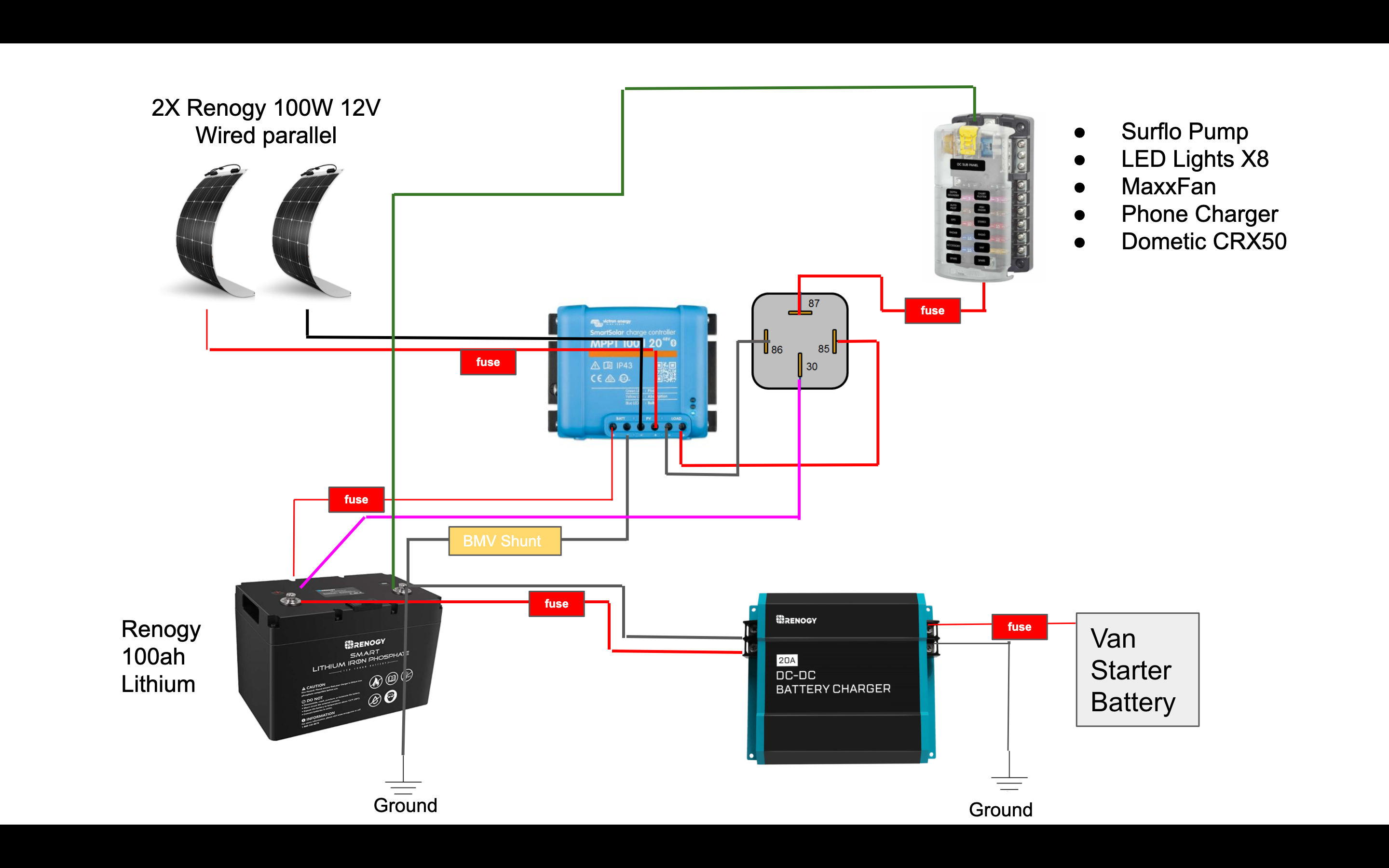
I have added a relay switch between my MPPT 100/20 and my loads. I was experiencing power outages when the compressor of the fridge kicked in. Must have been drawing more than the 20 amps the MPPT is rated for.

I have installed the BMV shunt.

I'm 90% sure I have the relay correct as my loads all work and I can turn them all on at the same time without the MPPT shutting off the load state. Furthermore, when load state of the MPPT is turned off manually, the loads turn off as well. It is worth noting that the MPPT no longer registers load current. Perhaps this is expected with the addition of the relay?

However, I think my shunt is in the wrong spot. The BMV It is reading battery voltage and current into the battery. However, it does not measure consumption. I have "infinity" time left in my battery

Could you please confirm the relay looks ok and that the MPPT not registering load anymore is expected?

AND

Could you please help with the Shunt placement? Maybe on the green wire in my attached diagram? I currently have it between battery and MPPT

Best wishes,

Mike


BMV Battery Monitor
2 |3000

Up to 8 attachments (including images) can be used with a maximum of 190.8 MiB each and 286.6 MiB total.

2 Answers
Matthias Lange - DE avatar image
Matthias Lange - DE answered ·

This is not the diagram I gave you.

The negative of all load/chargers have to be at the "Loads/Charger" side of the shunt.

The MPPT can now only register the current of the relay but you have the BMV for that now.

1 comment
2 |3000

Up to 8 attachments (including images) can be used with a maximum of 190.8 MiB each and 286.6 MiB total.

bendermichael avatar image bendermichael commented ·

I'm not very good at following directions. I went back and looked and your diagram is very clear. All seems to be working. Thank you! Where do I send the beer?

0 Likes 0 ·
dazey77 avatar image
dazey77 answered ·

as above, your diagram is certainly incorrect Re: the shunt


If both ground points are the chassis then the shunt would go between the battery -ve and the ground point. Remove the negative cable running between ground points.


At this point it will measure all load in/out of the battery (not necessarilly the load being drawn by the system as some will come from the MPPT)

2 |3000

Up to 8 attachments (including images) can be used with a maximum of 190.8 MiB each and 286.6 MiB total.