question

obay avatar image
obay asked

MultiPlus providing power on AC input when grid is disconnected?

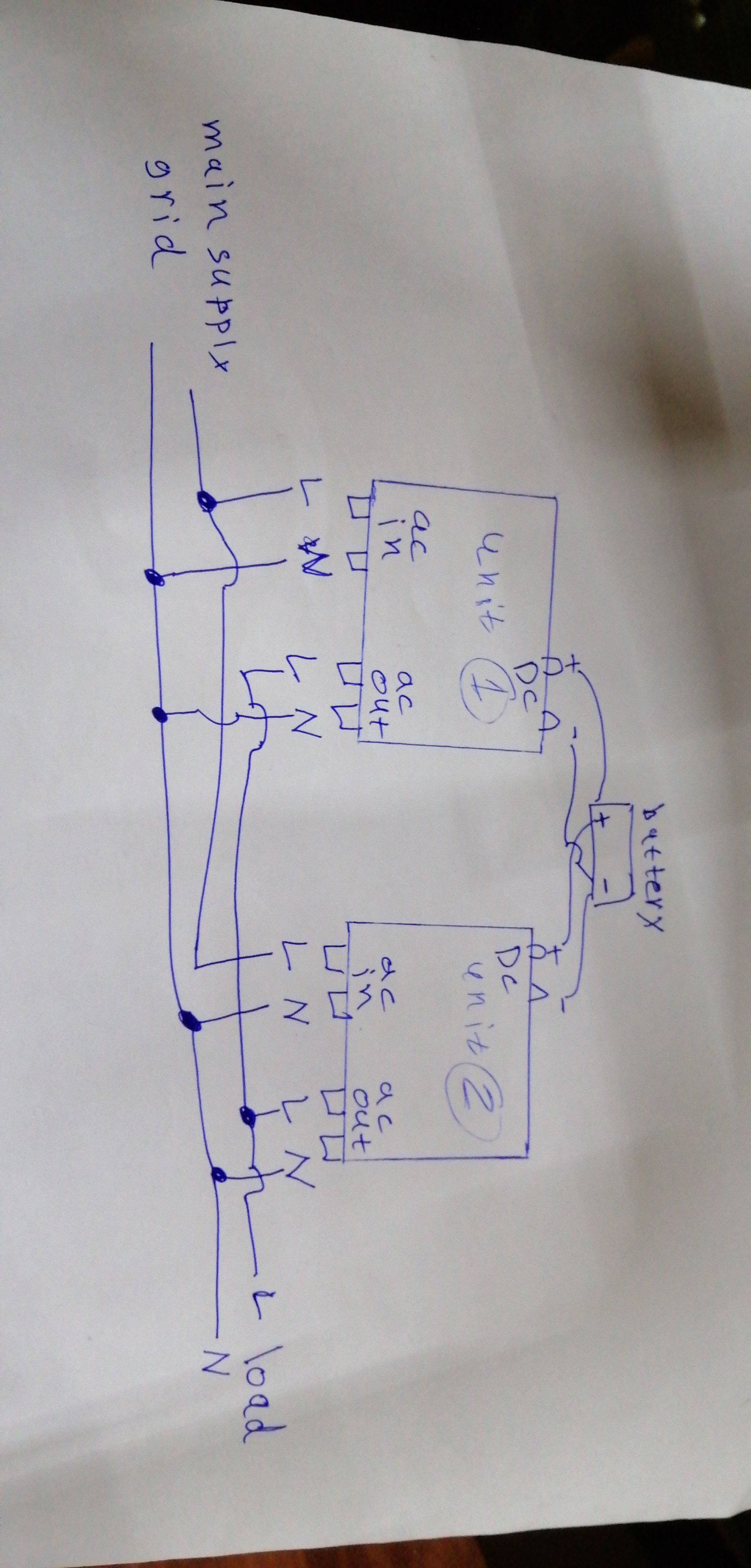
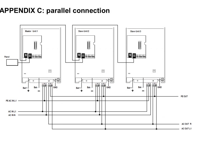
I connected 2 multiplus compact inverter/charger in parallel.

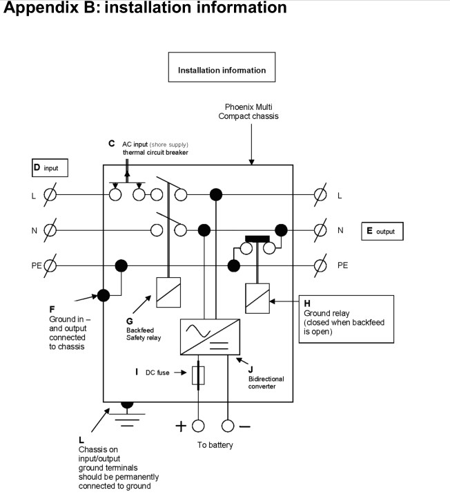
i configured it correctly , my problem when grid off , inverters return power to AC-IN line and to the all main table of electricity ,


multiplus 1600/24 ,

i use 4 12v 200ah batteries ( power bank 24v 400ah ),
2 inverters upgraded to the last FW.


i tried to disconnected the system and reset setting and turn it in stand alone mode and the same problem ,


i tried to downgrade FW and the same problem ,

can anyone find solution for me ( note : one of the inverter when grid off and on make big noise for seconds then sound normally , i check my connections its right ,


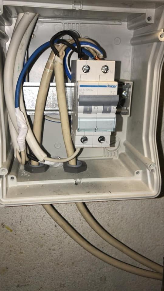
i have main table , and loaded divided to switches , one switch for ac in and one for ac out ,


i connected wanted load to ac-out , ac-in switch go to roof shed to switch breaker that feed ac-in 1 and ac-in 2 , ac-out 1 and ac-out2 go to switch breaker and then to main table connected to ac-out switch , but when grid off - the inverters feed the ac-in lines and unwanted load.


pls help

MultiPlus Quattro Inverter Charger
2 |3000

Up to 8 attachments (including images) can be used with a maximum of 190.8 MiB each and 286.6 MiB total.

3 Answers
Daniël Boekel (Victron Energy Staff) avatar image
Daniël Boekel (Victron Energy Staff) answered ·

Hi @Obay

You've asked this question multiple times, and also on Facebook.

The answers have been the same every time:

-Please correct your wiring, do -not- connect Neutral from input to output of the inverters.

-to test the inverters, connect them in stand-alone mode (just unplug the input/output of one inverter and program the inverters into stand alone mode) and check both inverters to work correctly

Some extra ideas:

-the (wieland) AC-connectors used on these small inverters are easy to get Neutral / Phase swapped, please double check this. (disconnect one of the inverters to make sure

-if you don't succeed, please get a Victron installer to help you with this. Also your dealer / distributor is the first point of contact for help with technical problems. He / she can judge if there is a problem with the unit or not, and if it needs repairing.

2 comments
2 |3000

Up to 8 attachments (including images) can be used with a maximum of 190.8 MiB each and 286.6 MiB total.

obay avatar image obay commented ·

dear i asked many times cause there is no answer , my connection its right 100%,

i tried to make it stand alone and same problem , both of them same still same problem

do u think its error 24 ( feedback safety relay fault )?

if yes , can u send me diagram of the relay and where it located and the type of it ?

and what the cause of fault for this 2 relays ?

note: i have no dealer near to my country , and also all way banned u know cause covid19

0 Likes 0 ·

Hi @Obay

The pictures you posted are not correct wiring:


Please get an electrician to help you with this.

0 Likes 0 ·
obay avatar image
obay answered ·

So i dont have feedback relay failure?

1 comment
2 |3000

Up to 8 attachments (including images) can be used with a maximum of 190.8 MiB each and 286.6 MiB total.

Hi @Obay

I cannot tell you: first your wiring has to be corrected. Incorrect wiring can give all kinds of errors.

And when the feedback relay is defective, the unit will not feed back, but go into error.

(although the relay is called 'feedback relay' due to historical reasons, it really is just the relay connecting the input to the system)


I'd start with one inverter:

-no AC connections, only battery, no errors? next step

-AC input connected also, no errors? disconnect them again

-AC output connected (and battery) no errors?

-AC input + output connected.

after testing both units this way, program them to be in parallel mode again, and run the same tests but with AC connections to both units.

0 Likes 0 ·
mikeb avatar image
mikeb answered ·

Hi

I agree with Daniel the wiring is not correct from this diagram


The inputs and outs are all connected together


1587290384536.jpeg (1.0 MiB)
2 comments
2 |3000

Up to 8 attachments (including images) can be used with a maximum of 190.8 MiB each and 286.6 MiB total.

obay avatar image obay commented ·

dear that not the main problem cause i made switch breaker for input and switch breaker for ac output , same problem , we still have two choices : 1 : the main cause in N same out N or 2 ; feedback relay fault or 3 unknown cause

but if u remove front piece of multiplus they draw the connections and in draw they used same N

0 Likes 0 ·
klim8skeptic avatar image klim8skeptic ♦ obay commented ·

"but if u remove front piece of multiplus they draw the connections and in draw they used same N "

You are better off looking at the manual.

0 Likes 0 ·
multuplus-a.jpg (61.2 KiB)
multuplus-b.jpg (43.5 KiB)