question

Edouard Lafargue avatar image
Edouard Lafargue asked

Heavy RFI Noise on Victron MPPT 150|70

I updated a radio site from using a MPPT 75|15 charger to a much heavier duty 150|70, connected to the same 1kW panel installation. The 75|15 could charge at 220W maximum (12 V battery), and the 150|70 goes above 600W with no trouble, which is great.

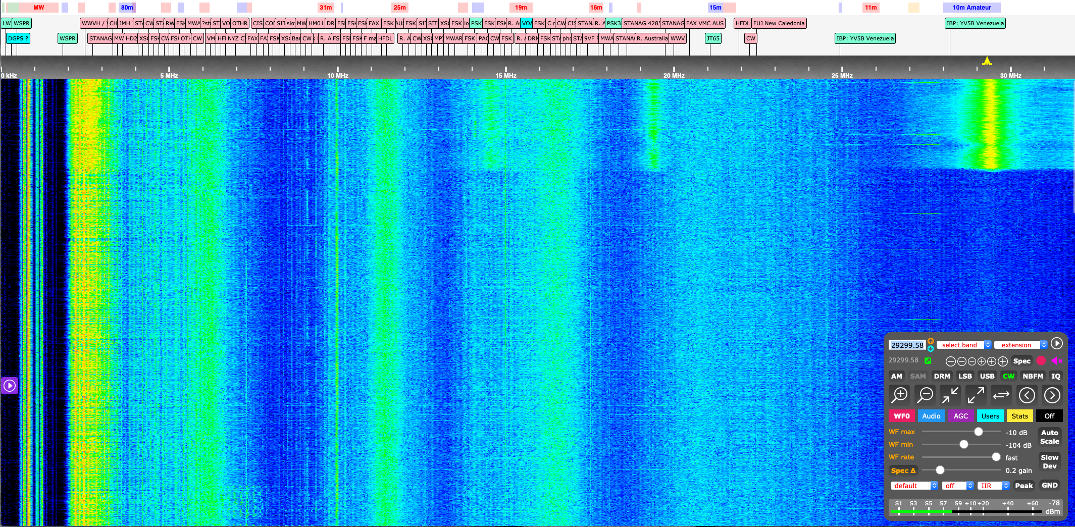
On the flip side, the 150|70 charger is awfully noisy from a RF standpoint, which is a real problem for a radio site (mostly HF), Below is an example of a nearby HF wideband receiver (antenna about 10 meters from the charger) and what happens when the panels are connected: I think the picture is self-explanatory, the charger is powered up and starts charging at 650W. Strong peak at 29.5MHz with harmonics all over the place (the actual fundamental frequency might be above 29MHz but that's what this radio sees). I am currently experimenting with various RF filters, no conclusive results so far. Note that this site is already noisy, but the Victron really stands out.

This is consistent with the various articles on this forum about people seeing dramatic reductions in range on AIS and interference on VHF as well.

Victron, any specific investigations I could be doing to attempt a few mitigation measures?


MPPT Controllers
2 |3000

Up to 8 attachments (including images) can be used with a maximum of 190.8 MiB each and 286.6 MiB total.

4 Answers
Edouard Lafargue avatar image
Edouard Lafargue answered ·

As a follow up: after more measurements, it looks like most of the RFI is radiated through the solar charging wires, which makes sense. Are there good filter designs out there that could be used to improve the situation?

2 |3000

Up to 8 attachments (including images) can be used with a maximum of 190.8 MiB each and 286.6 MiB total.

Edouard Lafargue avatar image
Edouard Lafargue answered ·

Second follow up: inserting a large common mode choke on the solar panel cable close to the charger does reduce the RFI, to the point it is not a significant problem anymore. My setup peaks at 700W (battery charging current limit), so I have not tested above that power, but with a careful choke design I was able to get things back under control. It's too bad the SmartSolar charger does not have a better built-in common mode filter design internally, but given the size of the filter that was necessary to get results, it looks like it wouldn't be possible.

I wish Victron had more guidance about this in their technical documentation...

1 comment
2 |3000

Up to 8 attachments (including images) can be used with a maximum of 190.8 MiB each and 286.6 MiB total.

jamesn2 avatar image jamesn2 commented ·
Can you comment on how you chose your choke? I have a pair of 150/100 chargers that will running at full output.
0 Likes 0 ·
dadshooter avatar image
dadshooter answered ·

I have resolved this issue. The MPPT switching of mosfets can create RF if DC and AC earths are not correct. Put simply the switching of the Mosfets to convert a high voltage to a lower voltage generates an Alternating current in the solar panel circuit. Below is a method of stopping these currents becoming an RF issue

Really important The solar panel Positive and Negative wires are run next to each other with ABSOLUTELY NO earth connections in the solar panel wiring circuit. The frame of the solar panel is a separate safety earth.

The main Earth in the circuit is at the Negative battery Terminal. But if the cable length from MPPT is say 5m to battery and 1M to earth then even though there is a low resistance in the cable it can create an RF antenna of 6M. The simple work around is to move the MPPT charger so this antenna is very very short. say 100mm cable to earth then a short cable from the earth piont to the battery . Both cables need fuses.

Not sure of different country wire standard but if you have to have a long cable + earth for the DC circuit then try a short bypass cable for the RF to earth . Think it should have a dc blocking by-pass capacitor selected for the frequency your trying to reduce inference. worked for me.

One more issue is to measure the DC voltage between Solar panel Negative and Positive outputs with respect to the Solar panel frame earth. There should be no voltage with respect to earth on either Try open circuit first then MPPT device on load.

A DC voltage between the solar panel frame earth and say the Negative of a solar panel is a real problem . What is happening is the panel wiring insulation breaks down inside the solar panel and a resistamce conection to is occuring to the Solar pannel frame . This is why it has to be earthed for safety. This is a common failure.

The panel fault must be removed.

The simple way is to make an educated guess by the use a proportion method.

4 x 30 volt open circuit voltage solar panels in series produce 120 volts. If one of the solar panels is leaking curent to the solar panel frame and you measure 55 volts then the fault is nearly half way in the circuit = Number 2 panel . Do not try and measure the current if you have a voltage. you will blow your meter up.

The reason for this RF noise in this situation is that an earth has been made by the faulty panel to earth part way in the Solar panel circuit

Thus the currents are not equal in Positive and Negative be wires. Oscillations cane occurs and depending on the resistance of the leakage to ground you have an antenna for 1 or many RF channels. But the oscillations have harmonics. My guess is that the MPPT is switching at 200K Hertz. got to web site calculator.

Would be interested to see if Victron was to include in the Android app a method to select different Switching frequencys would also help remove individual interference problems that the above does not resolve.

Hope this helps.

2 |3000

Up to 8 attachments (including images) can be used with a maximum of 190.8 MiB each and 286.6 MiB total.

pmano avatar image
pmano answered ·

I am fighting this issue right now. Many ferrite chokes later, shielding, grounding configurations.


@dadshooter could you please clarify:


Really important The solar panel Positive and Negative wires are run next to each other with ABSOLUTELY NO earth connections in the solar panel wiring circuit. The frame of the solar panel is a separate safety earth.


below are wire diagrams and some multi meter tests I conducted.


also I tested a single panel then two, three and four in series, in VOC test with one lead attached to the series in OC and one lead to panels ground hole. No voltage.

I only see voltage when the MPPTs are in-line and acting as load to panels.

I temp disconnected the ground wire connecting the mppts/inverter to the solar combiner box for these tests. The combiner is still grounded to earth.
5f9faf81-4c4f-4995-8817-a276e08b3377.jpegf94da6ae-857b-4d1d-a570-4bcc48a9e70c.jpeg
* 4 panels in series, voltage between + and -, VOC

465f2a5d-849f-478d-8478-228af452dc70.jpeg

* 4panels in series, ISE and multi meter connected to frame on black lead and red lead in series with 4 panels. 0.0421 vdc between panels +\- and frame. 7.39 amps ISE
24ab4220-80c5-4e18-ba32-d365305b050a.jpeg

*4 panels in series, - lead on frame, + lead on panel -, showing 0.0936 vdc between panels frame and -.

There is a earth ground still attached to the frame rails*

d6dd9f71-cee5-4398-ab81-cdf6fbf0ba10.jpeg


2 |3000

Up to 8 attachments (including images) can be used with a maximum of 190.8 MiB each and 286.6 MiB total.