question

neil-1 avatar image
neil-1 asked

Multiplus-II: How to connect LCD display ribbon cable orientation / polarity?

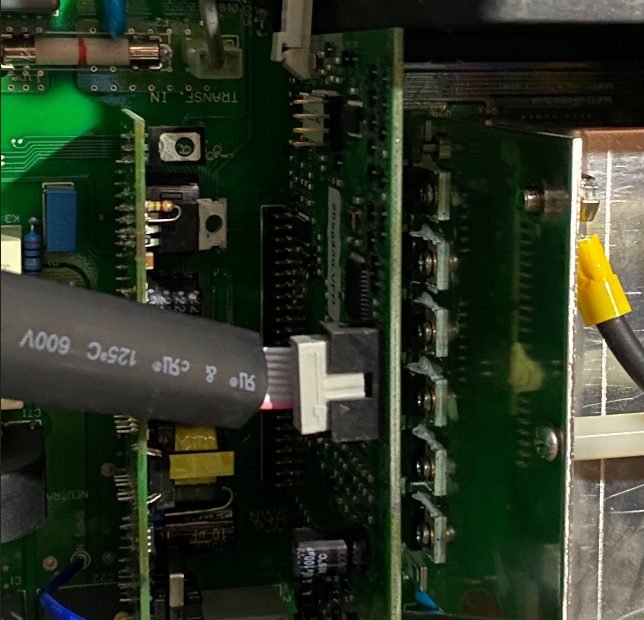
Multiplus-II: The header plug on the ribbon cable that connects the LCD display to that internals does not have any physical limit on how to connect it to the LCD display (it can be connected in two orientations, and one is wrong).

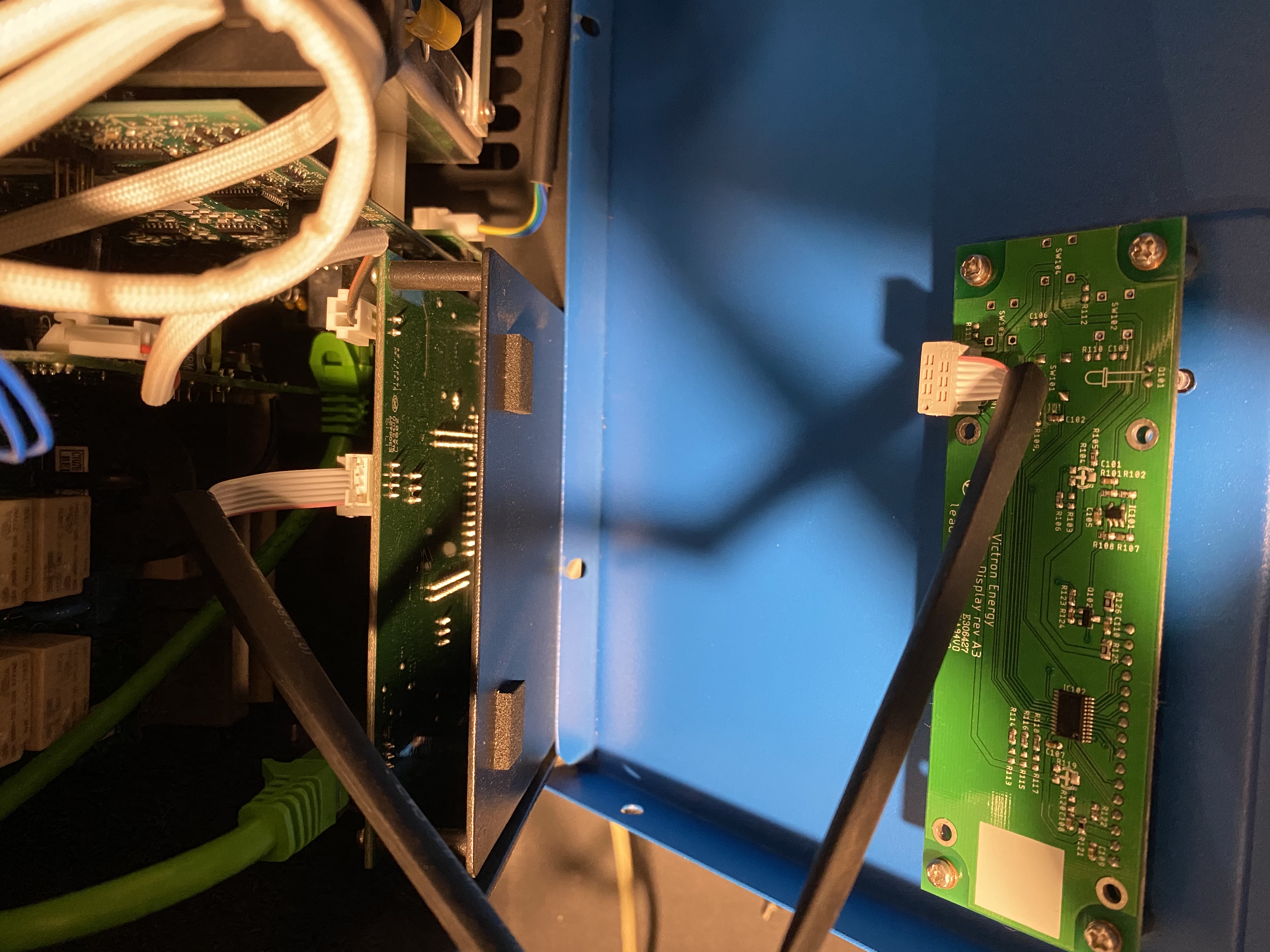
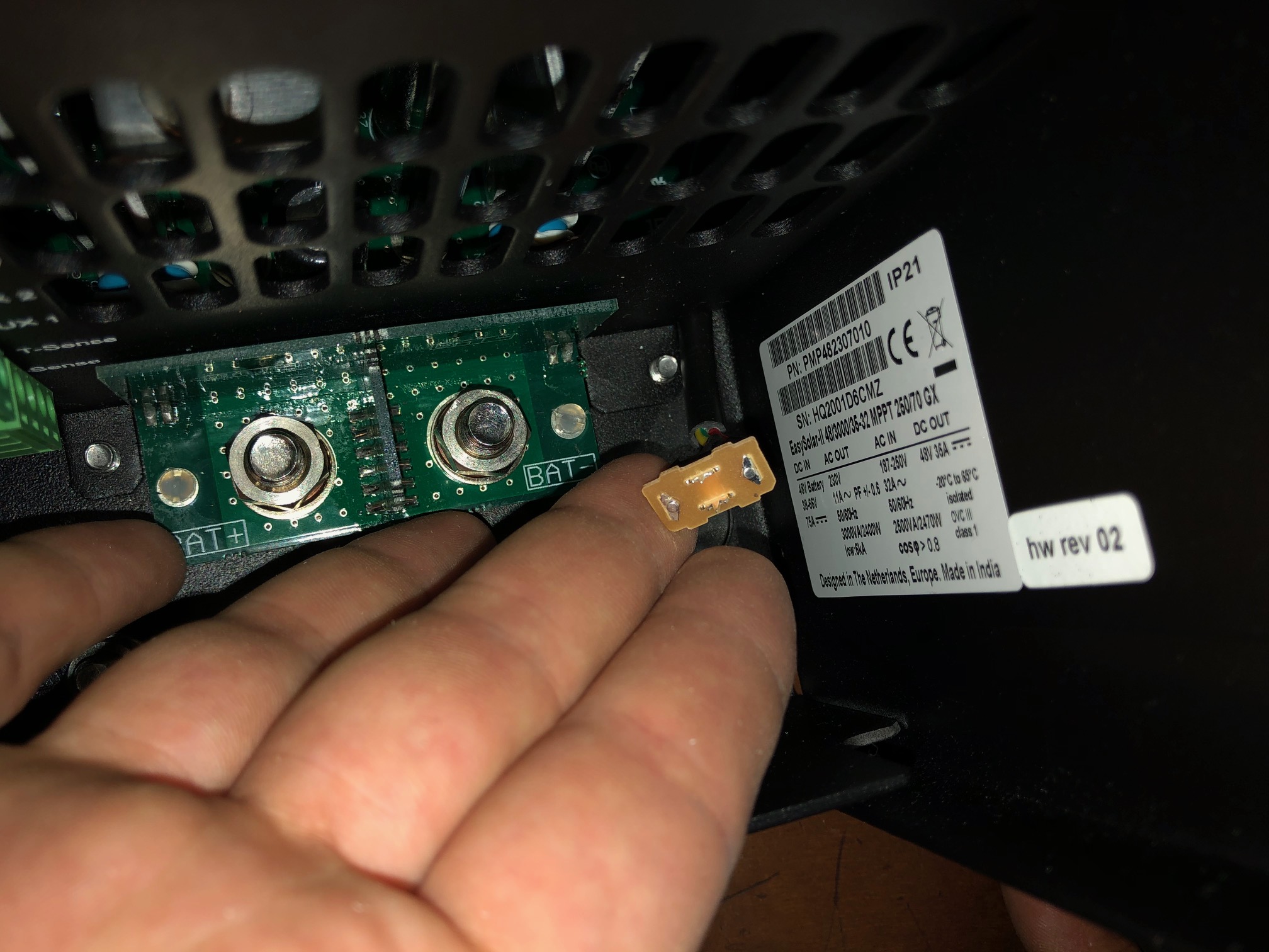
After removing the ribbon cable (to do emergency repairs during lock-down) I am unsure how to reconnect the ribbon cable to the LCD PCB.

The ribbon cable does have a red line, and there is a + printed on the PCB, but it will be a risk to connect this without certainty.


Can someone please advise how to connect the ribbon cable correctly to the LCD PCB?

We are in lockdown and I need this inverter to work ASAP.

Multiplus-II
2 |3000

Up to 8 attachments (including images) can be used with a maximum of 190.8 MiB each and 286.6 MiB total.

2 Answers
Guy Stewart (Victron Community Manager) avatar image
Guy Stewart (Victron Community Manager) answered ·

Hi @neil@interlock.co.za

I have been in this situation myself. The good news is, incorrect orientation will not destroy anything, so it can be reversed, it just won't work until correctly connected.

There is a subtle 'key' on the cable, and socket. It is a visual cue though and it does not prevent reverse connection.

The correct arrangement is shown for the MultiPlus-II:

8687-screen-shot-2020-03-27-at-113933-pm.jpg

Here for the MultiPlus-II GX:

8688-img-4515.jpg

Also probably a good time to mention these units were designed so that opening them should not normally be necessary. The required connections are made on the bottom.


2 |3000

Up to 8 attachments (including images) can be used with a maximum of 190.8 MiB each and 286.6 MiB total.

neil-1 avatar image
neil-1 answered ·

Dear Guy, THANK YOU very much for the info. Exactly what I needed.

We had to open the unit because the main power switch (on-off-charger) was broken (out of the box - the switch was pulled open and the rocker missing), and to replace it I had to remove the cable and solder on a new switch. No biggie. :-)

Broken switch with my repair below.


Your second photo showing the blue cover is where I had the problem. Your picture is perfect.

Thank you!

:-)


img-0109.jpg (499.7 KiB)
img-0108.jpg (104.3 KiB)
img-0126.jpg (107.6 KiB)
2 |3000

Up to 8 attachments (including images) can be used with a maximum of 190.8 MiB each and 286.6 MiB total.