question

Stefanie (Victron Energy Staff) avatar image
Stefanie (Victron Energy Staff) asked

Schematic wiring and setup Cerbo GX, VE.Bus BMS, LiFePO4, Multi

Since yesterday the Cerbo GX manual is ready to download here.

Was a bit surprised that the Cerbo is powered by the Load disconnect from the VE.Bus BMS, but that is how the manual reads.
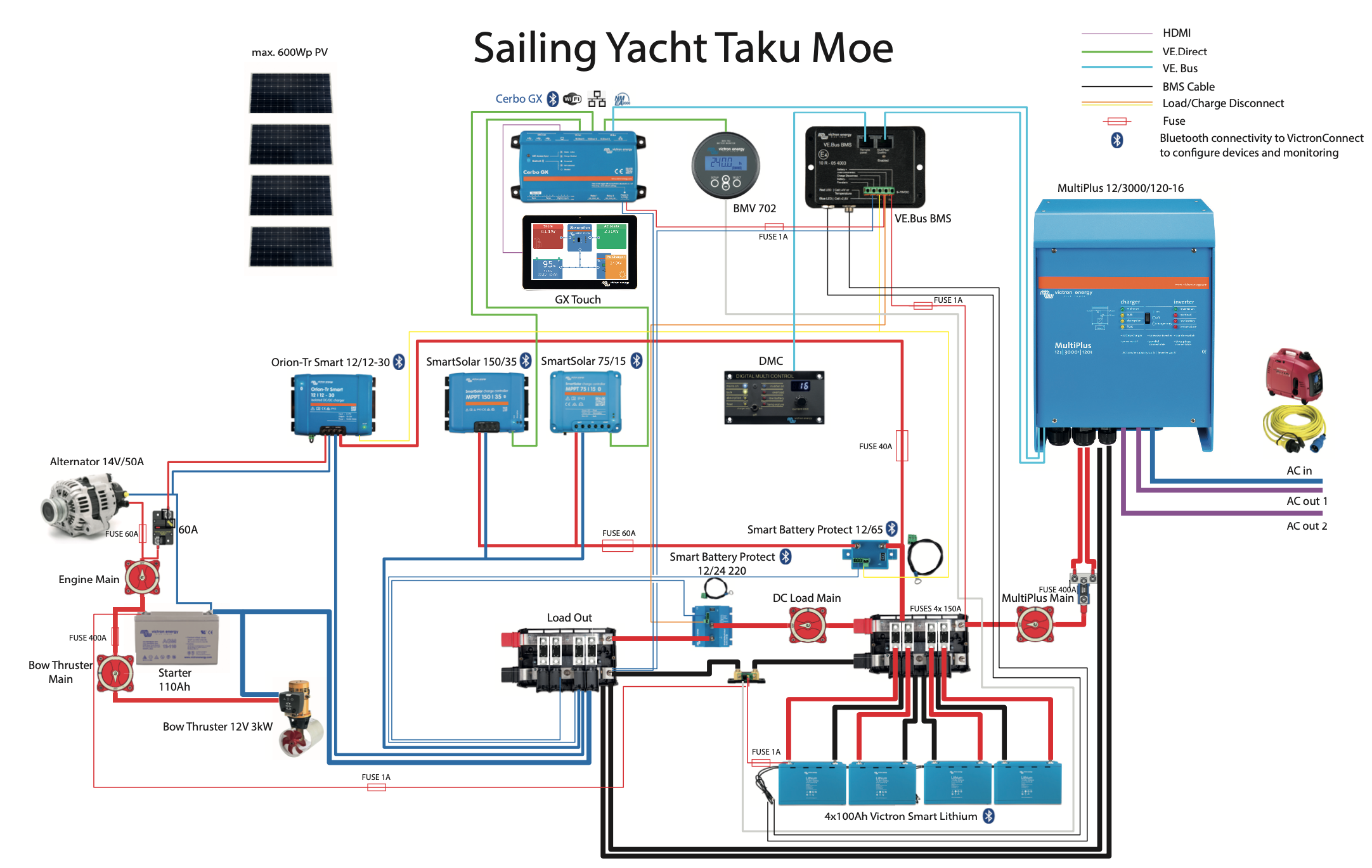
I finally was able to finish the schematic wiring for the new setup.


Maybe someone can have a look and check the schematic and see if it is acceptable?


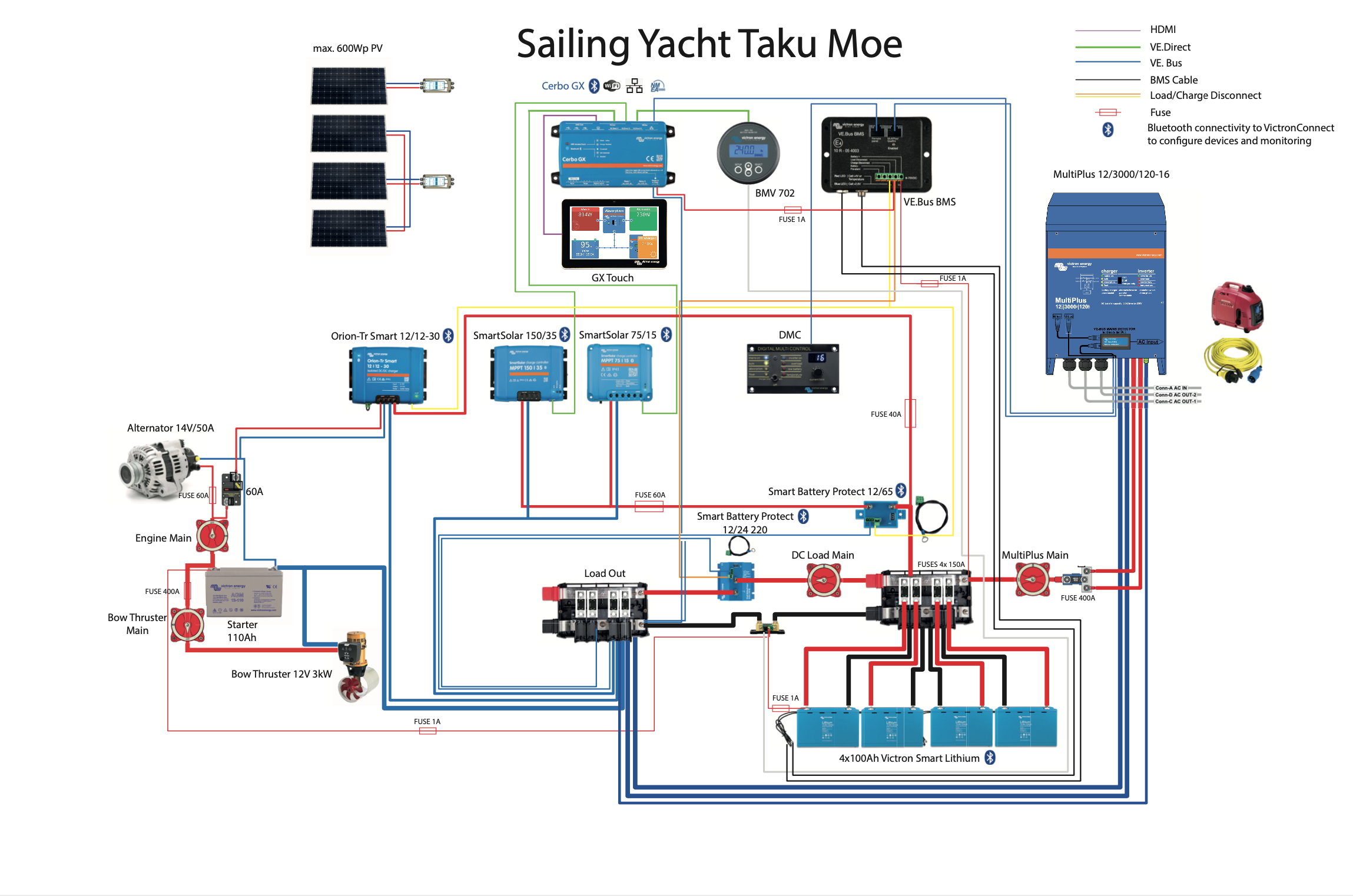
takumoe_12v_powersystem_v7.pdf


schematics
3 comments
2 |3000

Up to 8 attachments (including images) can be used with a maximum of 190.8 MiB each and 286.6 MiB total.

medavdsn avatar image medavdsn commented ·

What did you use to create your diagram? Working on designing a system for my travel trailer and would love to create a diagram like that for my install.

0 Likes 0 ·
Stefanie (Victron Energy Staff) avatar image Stefanie (Victron Energy Staff) ♦♦ medavdsn commented ·

Hi @medavdsn,

I've been using Adobe Illustrator for drawing the lines and placing the images.
The icons/images are simple images collected from Victron Schematics and photos.

0 Likes 0 ·
medavdsn avatar image medavdsn Stefanie (Victron Energy Staff) ♦♦ commented ·

I was hoping you'd say you had a library of icons for Visio. Oh well, manual it is.

0 Likes 0 ·
5 Answers
Justin Cook avatar image
Justin Cook answered ·

@Stefanie I just spent about 30 minutes looking over this and I am both pleased and somewhat astonished to be able to say that I don't see anything wrong with it... not that I'm the end-all authority on things by any means, but I'm quite used to being able to look at something for a moment and say "ah, nope, this and that won't work" and you've broken that streak. Well done!

2 comments
2 |3000

Up to 8 attachments (including images) can be used with a maximum of 190.8 MiB each and 286.6 MiB total.

Thank you @Justin Cook - Bay Marine Supply USA for your time!

I was surprised to see someone commenting on my post because I thought I had it deleted already after reading the community guide lines. Seems that did not work ;-)
Because the thread is still up, I just updated the diagram to its final version.

Meanwhile I also got the ok from my Victron dealer and put the order.


0 Likes 0 ·
Justin Cook avatar image Justin Cook ♦♦ Stefanie (Victron Energy Staff) ♦♦ commented ·

@Stefanie yes, the Guidelines discourage posting/asking for schematics just because it's not technically what the forum is for, but we'll rarely actually delete such a thing... it's more just a matter of managing expectations given that we'll always prioritize technical issues and so no one might have a chance to look at it/give feedback in a reasonable amount of time/ever.

It helps when you're a pretty well-established member of the Community who's put in a significant amount of time helping other people, too :) Cheers!

0 Likes 0 ·
Rob Fijn avatar image
Rob Fijn answered ·

@Stefanie, Always good to read some one else their design, thank you. I would take the Battery+ of the VE.Bus BMS from the load side of the DC Load Main switch. This would give the possibility to switch the load really OFF from the batteries.

Regards, Rob

2 comments
2 |3000

Up to 8 attachments (including images) can be used with a maximum of 190.8 MiB each and 286.6 MiB total.

Rob Fijn avatar image Rob Fijn commented ·

@Stefanie, some more.. Victron say you should not connect the Battery- on the VE.Bus BMS to the negative, as this is already connected via the UTP cable. You want to prevent ground loops.

Also I do not see the AC Detector. This to start the Multi when this is shutdown in case of under voltage alarm, otherwise the Multi will not start when AC in is applied.

Regards,

Rob

0 Likes 0 ·
Stefanie (Victron Energy Staff) avatar image Stefanie (Victron Energy Staff) ♦♦ Rob Fijn commented ·

Thank you @Rob,

there is a manual switch for the VE.Bus BMS to disconnect. I forgot to put that into the schematic.
Battery minus on the VE.Bus BMS is not connected to the battery negative.

There is a updated version of the schematic to it's final version with AC detector.

0 Likes 0 ·
nebulight avatar image
nebulight answered ·

I'm also surprised to see how the Cerbo is wired to the ve.bus BMS LVD as in previous installs/guides, they show it powered from the main DC bus so you can still receive alerts and act upon them. This of course comes at a risk as the load, while small, can still drain a depleted battery if you fail to act on the alerts.

2 comments
2 |3000

Up to 8 attachments (including images) can be used with a maximum of 190.8 MiB each and 286.6 MiB total.

Exactly @nebulight,

One small problem with providing system wiring diagrams, is that there are usually options and design decisions that are not fully explained.

In the case of a Victron lithium battery, the consequences of discharging the battery below the safe low voltage points are so severe/damaging that it is recommended that no loads (except the disconnection devices) are attached to draw down any further once the shutdown signal is sent.

Also note there is a new feature in the VE.Bus BMS, a pre-shut down alarm that will give some additional seconds delay, and some notice of system issues before disconnecting power to allow for the GX device to get the message. So that should help too.

0 Likes 0 ·

Hi @nebulight,

yes. I was wondering that myself. But the Cerbo manual clearly states that in a system with VE.Bus BMS power needs to be connected to LVD of the BMS. But in the end I think it makes sense and I'm on the safe side.

0 Likes 0 ·
mike-g avatar image
mike-g answered ·

Would someone explain how a 30 A DC-DC charger can effectively charge a 400 AH bank in a reasonable amount of time? I assume that the primary recharge source must be solar. It would appear that the alternator's only role is to charge the start battery. Why would you not use the alternator to charge the house bank, at a almost twice the rate of the DC-DC charger? Thanks.

8 comments
2 |3000

Up to 8 attachments (including images) can be used with a maximum of 190.8 MiB each and 286.6 MiB total.

nebulight avatar image nebulight commented ·

I can’t speak for everyone, but I have a 400ah 12v bank and I only use my dc to dc charger if solar is not producing and I have a dead battery. Basically for emergencies only. Truth be told I have had my dc to dc charger for over a year (not victron) and never have actually turned it on.

As for why not just link the starting battery to the house battery, there are several reasons but for me it was the ability to regulate the current as well as the voltage. Also since lithium can suck as much current as you give it, having a such a large draw on the alternator can’t be good long term.

0 Likes 0 ·

Hi @Mike_G,

the alternator is 50A. With losses it max out at around 35A. This is what I get from a alternator to battery charger in my old system to charge an 440Ah AGM battery bank.
As you can imagine, It never was able to charge up to 100%. But it also was never intended to do so because we completely rely on solar power. In 3 years time that worked perfectly for us and I guess it will do so also in a lithium setup.
Charging my batteries solely with the engine/alternator is no alternative for us and only come into effect in situation where there is no solar power at all and batteries are at the limit.

0 Likes 0 ·
mike-g avatar image mike-g Stefanie (Victron Energy Staff) ♦♦ commented ·

Thank you Stephanie and nebulight for the confirmation. Solar is the way to go if you have space for it. A properly sized alternator and voltage regulator is necessary if you don't.

0 Likes 0 ·
Justin Cook avatar image Justin Cook ♦♦ commented ·

@Mike_G, you should never charge an LFP house bank directly from an alternator due both to the very high -if not guaranteed- risk of burning up the alternator as well as the need for a carefully regulated charge profile; to a large extent this applies to standard Pb battery banks as well. This is why the DC-DC charger was originally invented to begin with.

As the referenced diagram shows, in this case there are clearly multiple charge sources, and the DC-DC charger is being used primarily to top-up the batteries while the engine is running. As a primary charge source, you're correct, 30A is undersized and anyone designing a system with a DC-DC charger as the primary charge source will inevitably add more chargers in parallel as necessary or use a higher-current charger.

0 Likes 0 ·
mike-g avatar image mike-g Justin Cook ♦♦ commented ·

"Never" is a pretty strong word, especially when it comes to boats;)

There are many scenarios where solar isn't practical as the primary charge source. Sailboats with limited panel space are just one example, and the one I'm most familiar with. Alternator charging can certainly be done with a lithium or lead house bank with careful design. However this is getting off topic and I appreciate Stephanie's drawing for its clarity and completeness.

0 Likes 0 ·
Stefanie (Victron Energy Staff) avatar image Stefanie (Victron Energy Staff) ♦♦ mike-g commented ·

Mike, charging our service bank through the main engines alternator never was an option for us when preparing for blue water sailing, simply because it's an old engine and we feel lucky that it still helps us in and out of marinas or anchorage. Environmental thoughts also play a significant role.
Primarily we use the DC-DC charger to protect the alternator and at the same time have the batteries topped up when we're motor sailing for whatever reason.

To be on the safe side we have a small gasoline generator and that one is good enough to pull out 70A from the MultiPlus charger. In our old setup we never had to run our engine or the genny to charge our batteries. PV did a good job so far and always kept our batteries at least once per day at 100% SoC and never below 80%. Of course this will change soon when we start electric cooking. That's why we go for Lithium.

0 Likes 0 ·
Justin Cook avatar image Justin Cook ♦♦ mike-g commented ·

Understood "never" is a strong word, but I'll stand by it. Never *directly* from the alternator.

0 Likes 0 ·
anthem avatar image anthem commented ·

it depends on the perspective you are coming from. If you are on a sailboat with a 40hp engine, you arent going to be able to put on a Leeve Neville 270amp hour alternator. If you are on a motorboat or motorhome with 500hp engines, then yes you can put on larger alternators.

And there are many setups where an alternator charges the house batteries and start batteries (battery combiners/isolators, duo charge, etc). there are also configurations with multiple alternators (one for each engine, or even two alternators on one engine).

I will agree and disagree with Justin on the alternator charging. I agree that almost /none/ of the alternators provided OEM should be used to charge lithium batteries (or they should be derated significantly). Because LiFepo4 batteries will use the entire amount they can up until they are nearly full. That extended time of non-stop use will burn up many alternators if they were not designed for heavy duty non-stop use. However, there are many alternators that were designed to be used (they will usually say transit bus rated etc) non-stop and they can easily handle the charging needs of a lifepo4 bank. Leeve Neville 4400 series (2800 even for lower power). CE Neihoff has massive 300/450 amp units, Delco-Remy 28SI, 55SI, 50DN are all heavy duty alternators that can handle constant use, and Balmar who does a lot in the marine world, as does Mark Grassley.

But if you do charge from alternator - you have to take in to consideration that you need to stop the charging when it gets full. And you have to do it safely without frying your alternator. There are two ways to do that - one is to hook your start (or any lead acid) battery in line, so that when you disconnect via BP, ArgoFet, Isolator, whatever - that the LA battery is still inline and can accept the alternator current when your lifepo4 bank goes offline. the other way is to charge just the lithium bank and use a smart regulator like the Balmar MC614. And program the MC614 for lifepo4 settings and disconnect the field wire. It still might be best to have a lead acid battery in line here though - as disconnecting the field is the way to do it. However if it somehow fails, and your bms disconnects the entire battery circtuit, you run the risk of frying the diodes on the alternator.

But in general - for a lifepo4 battery bank on a large boat or motorhome that has the capability - using the alternator to charge the battery bank is the fastest and easiest way to get large amounts of charge back in to the bank.

0 Likes 0 ·
freighttrain avatar image
freighttrain answered ·

I realize this thread is getting older but I want to point out for future readers that the diagram offered by the OP uses a Battery Protect to disconnect the charging sources. This is unacceptable. The Battery Protect solid-state relays are not designed for this purpose. Instead, use a Cyrix Li-charge relay.

1 comment
2 |3000

Up to 8 attachments (including images) can be used with a maximum of 190.8 MiB each and 286.6 MiB total.

nebulight avatar image nebulight commented ·

The current can flow in the opposite direction by installing it backwards.

0 Likes 0 ·

Related Resources

Additional resources still need to be added for this topic