question

weisenstein avatar image
weisenstein asked

Why the RCD trips imminently when MultiPlus II is in inverter mode!


Hello everybody,

I working for a university laboratory and this is my first project with Victron components. I am wondering, that I am obviously the only one with this kind of RCD tripping problem. I did not find any contribution in the community place. So I want to give you an extensive overview of our system and the problem.

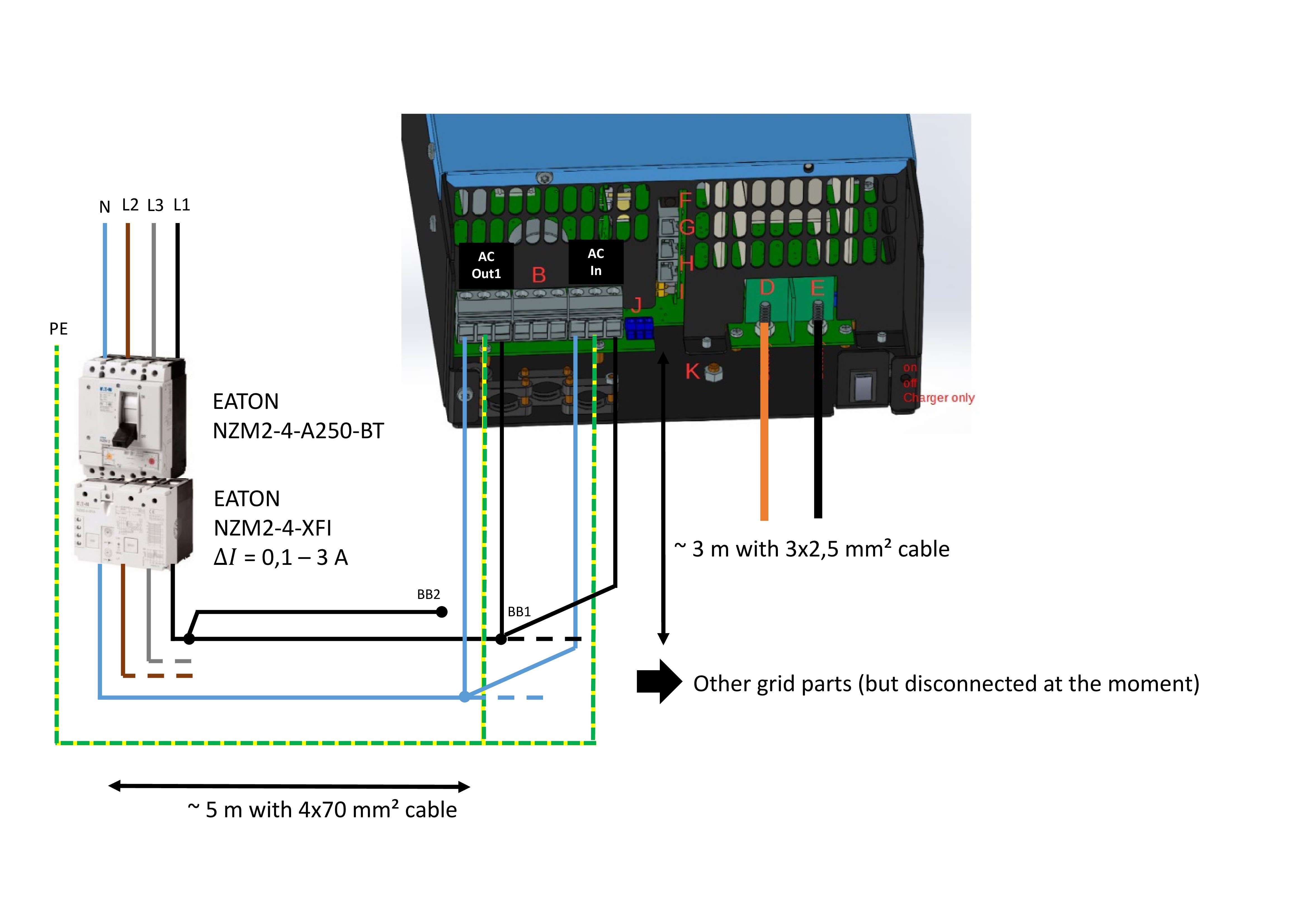
Our battery-system contains: 3 x MultiPlus2 48/3000/35-32 with 3 x PYLONTECH LiFePO4 48Volt - 3,5 kWh Battery and 3 x Venus GX and is embedded in a test grid with other applications.

In the test grid, neutral and protection wire are separated and the whole test grid is protected by a RCD (Typ A, 250 A, fault current 0,1 A – 3A) due to personal safety in a test area. For the test of the battery-system, I disconnect all other applications from the grid. I only want to charge and discharge the battery. AC Input and AC output1 of the MultiPlus2 are connected to the same busbar.

In charging mode, everything works well. If I switch into inverter mode (using the Venus GX settings), the RCD trips immediately. This happens with all MultiPlus2 and also when I set the allowed fault current of the RCD to maximum (3 A!). When I connect the MultiPlus2 to a grid without RCD, the inverter mode works as well. But, due to safety reasons, we need to have an RCD. And according to the manual, it should be possible.

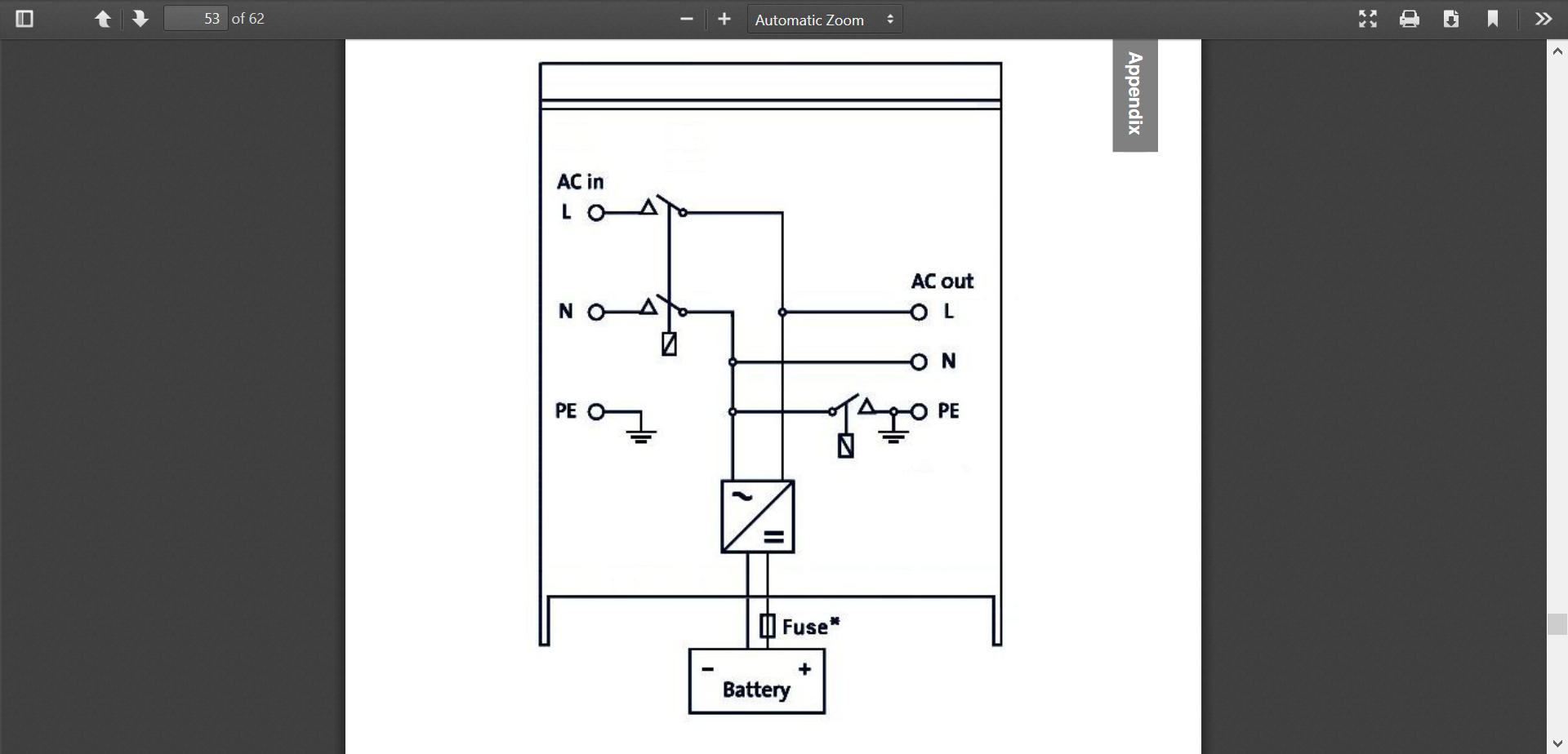
According to the online manual of the MultiPlus2 (Version 9, December 2019), a type A RCD can be used. According to the manual which comes with the inverter (Version 2, April 2019), only a type B RCD is allowed (@Victron: What is right? I only bought the victron products because of that information in the online manual!).

My question: Will the RCD won’t trip if I buy a (expensive) type B RCD?

I don’t think so. Normally the type B RCD is more sensitive, i.e. it trips in more failure cases.

What else can I do? Disconnecting the earth at the inverters (bad idea)? Can MultiPlus2 work with RCD at all?

I hope somebody having good advice for me.

Best Regards

M. Weisenstein

Multiplus-II
4 comments
2 |3000

Up to 8 attachments (including images) can be used with a maximum of 190.8 MiB each and 286.6 MiB total.

Rob Duthie avatar image Rob Duthie commented ·

Hi

I have the same system setup with no issues at all. Can you supply a wiring diagram of how its being done?

Note: On RCD protected supply generally you have one RCD per 3 outlets due to cable capacitance and leakages etc.

Type A is Ok it is designed for AC and DC

You talk about setting RCD fault current to 3 Amps? They don't have set points!


Regards

Rob D

NZ

0 Likes 0 ·
Riaan Barkhuizen avatar image Riaan Barkhuizen Rob Duthie commented ·

Agree with @Rob Duthie on the 1 RCD per input and another for the output. You should just watch out for a situation where you have two RCD's connected in series.

0 Likes 0 ·
weisenstein avatar image weisenstein commented ·

Hi, thank you for your fast reply andyour feedback. It is good to hear that in general the inverter can work with RCD Typ A.

I prepared the wiring diagram as you can see above.

The battery-system is a part of our test enviroment (thats the plan) and the whole test grid is protected by a industrial RCD (https://datasheet.eaton.com/datasheet.php?model=292344&locale=en_GB). This typ of RCD have set points for the failure current. Because of other application in the grid we need at least a minimum allowed failure current of 0,1 A.

Like I told you, I use the same busbar vor IN and OUT (busbar BB1 in the diagram). Of course I can connect the OUT to another busbar (and I will do today), e.g. BB2. But it is still in the protection area of the RCD. Myfeeling is that this will not fixing the Problem.

Because the battery-system is a part of our test enviroment and the whole power supply is protected by that RCD, I can not connect IN and OUT to diffrent RCDs.

Best Regards

Marco

0 Likes 0 ·
overview.jpg (833.3 KiB)
Daniël Boekel (Victron Energy Staff) avatar image Daniël Boekel (Victron Energy Staff) ♦♦ weisenstein commented ·

@Weisenstein

As Rob already wrote:

Please!! get an electrician and / or Victron installer involved here!!

0 Likes 0 ·
3 Answers
JohnC avatar image
JohnC answered ·

Hi @Weisenstein

This may well be related to the MEN switch within the Multis. I can't assist with the technicalities, but put it forward for consideration.

It can be turned off, but what you do there is for you and your electrician to determine..


1579768771521.png (336.3 KiB)
1 comment
2 |3000

Up to 8 attachments (including images) can be used with a maximum of 190.8 MiB each and 286.6 MiB total.

weisenstein avatar image weisenstein commented ·

Thank you. You are right this was the problem.


I read this in the past. But I thought that inverter mode does not mean to open AC in (and closing the N-PE connection).


0 Likes 0 ·
Riaan Barkhuizen avatar image
Riaan Barkhuizen answered ·

Hi @Weisenstein

If possible could you check the following?

"AC Input and AC output1 of the MultiPlus2 are connected to the same busbar. "

Repeat your test with separate busbars.

Best Regards

Riaan


3 comments
2 |3000

Up to 8 attachments (including images) can be used with a maximum of 190.8 MiB each and 286.6 MiB total.

weisenstein avatar image weisenstein commented ·

Thank you for your advice. My problem was the earthing of the neutral after setting the inverter mode via Venus GX.


I still think that it is possible to connect the MultiPlus2 as shown in the diagram (maybe I have to go to connect AC out2 instead of out1) to get the grid parallel connection we want, but I have to configure the EES first.


Thanks a lot!

0 Likes 0 ·
Daniël Boekel (Victron Energy Staff) avatar image Daniël Boekel (Victron Energy Staff) ♦♦ weisenstein commented ·

@Weisenstein

NO! do not connect a source (grid, generator) to the output of the inverter. DO NOT connect input to output.

Please get some training and support from you Victron Dealer / Distributor.

You WILL damage things and maybe people if you continue like this.


Also: read the documentation:

https://www.victronenergy.com/live/ess:design-installation-manual

https://www.victronenergy.com/upload/documents/Brochure-Energy-Storage-EN_web.pdf

0 Likes 0 ·
weisenstein avatar image weisenstein Daniël Boekel (Victron Energy Staff) ♦♦ commented ·

Ok I understand. Thank you for your feedback.

0 Likes 0 ·
Rob Duthie avatar image
Rob Duthie answered ·

Hi

As said by Riaan you must separate the in and outs.

You should get an the electrician to wire this!!!


Regards

Rob D

NZ

1 comment
2 |3000

Up to 8 attachments (including images) can be used with a maximum of 190.8 MiB each and 286.6 MiB total.

weisenstein avatar image weisenstein commented ·

Thank you. I understand your point. I am the responsible electrician man in our lab.


We want to use the system in parallel to the grid. For this, I have to configure the EES.

0 Likes 0 ·