question

olrik avatar image
olrik asked

Why connecting the Inverter and Solar Controller to the batteries in parallel?

Hello,

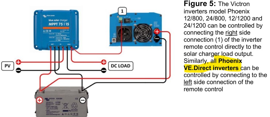
Smaller Solar Controllers providing one (1) connector for the Batteries and one (1) connector for the load. But with all larger installations, Solar Controller and Inverters are connected in parallel to the batteries not using the load connector, which even doesn't exist. That confuses me.

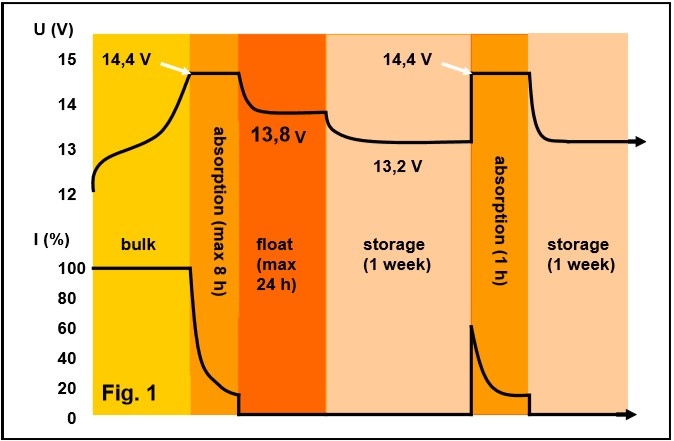
I understand that (one of) the purposes of the Solar Controller is to control the charging process of the batteries preventing over -charging and -discharging to increase the life time.

But connecting the Inverter in parallel to the Solar Controller how does the Solar Controller detects that the batteries are already fully charged if the inverter withdraws still current?

In other words, there are two (2) consumers getting load from the Solar Controller, how does the Solar Controller distinguishes between the different demand of them?

Secondly, in case the inverters withdraws more current the Solar Controller (better: the PV panels plus the batteries can provide (causing an over-discharging), which elements detects and disconnects the consumers?

Having a separated connector for the load, the Solar Controller can disconnect the consumer in case the batteries are discharged but continue to charge the batteries. After the batteries are recovered, the load can be connected again.

So the Solar Controller is "in charge of/responsible for" the batteries. But connecting the inverter directly to the batteries, the Solar Controller is bypassed.


Is my understanding correct or do I miss something?


Thanks in advance.

Regards

Olrik

MPPT Controllers
2 |3000

Up to 8 attachments (including images) can be used with a maximum of 190.8 MiB each and 286.6 MiB total.

4 Answers
klim8skeptic avatar image
klim8skeptic answered ยท

Hi Olrik,

" So the Solar Controller is "in charge of/responsible for" the batteries. But connecting the inverter directly to the batteries, the Solar Controller is bypassed."

Not really. There are plenty of ways to skin a cat.

Most inverters will interface with the mppt load terminals , and respond to a turn off signal.

Most inverters have programable low voltage cut outs.

If you are running an expensive battery, you should be running at the minimum a low voltage cut out, or some sort of BMS to protect the battery from over discharge.

2 |3000

Up to 8 attachments (including images) can be used with a maximum of 190.8 MiB each and 286.6 MiB total.

wkirby avatar image
wkirby answered ยท

In a small system you might not have an inverter. Just a few DC lamps, a small refridgerator and television set or radio. These can all be connected to the switched load output of the charge controller directly and they will be disconnected when the battery Voltage is low or some other parameter that the use chooses.
A battery monitor like a BMV would be nice, but the size of the system is too small to justify the expense, so the charge controller can be employed to just monitor the battery based on Voltage limits.

If you have a slightly larger system with an in verter, it is not possible to connect an inverter more than 250W - 500W to the switched load output terminals of the smaller charge controllers, the load current is too high. It must be connected directly across the battery.
However, it is still possible to enable or disble the inverter from the charge controller. You can set the Tx pin of the VE.Direct port to drive a signal high or low to enable or disable the inverter.
You could also use this signal to command a suitable relay which will turn loads on or off. The relay should be sized to accommodate the loads. Using a relay or contactor to switch an inverter on or off via its battery cables is a bit of a brute force way of doing it. If your inverter does not have a signal input to enable or disbale it then that is the ony option and probably OK for up to 500W inverters.
All of the Victron charge controllers have the "Virtual Load" facility.
This cable provides the signal output to control devices via the VE.Direct port: https://www.victronenergy.com/cables/ve-direct-tx-digital-output-cable

In much larger systems the cabling is structured and permanent and contactors or relays should not be used to switch inverters or large loads on or off. They should be contolled elegantly with control systems. A battery monitor is essential in these systems and it will be the master SOC reference for the system. Charge controllers will be controlled by the system to enable or disble charging.

2 |3000

Up to 8 attachments (including images) can be used with a maximum of 190.8 MiB each and 286.6 MiB total.

olrik avatar image
olrik answered ยท

Dear Kirby and Klim,


thanks for your advise and bringing a new perspective to it.

The solution to control the inverter by the Solar Charger will work with me to address the discharging of the battery below a certain value 8-)

But regarding my second concern - how does the Solar Controller identifies that the battery is fully charged and prevents overcharging?

The inverter still withdraws current to feed the active consumers so the Solar Controller has to continue to feed the inverter. Due to the combined feed of inverter and battery the battery still gets a voltage.

There is no control cable to "disconnect" the battery ...


Thanks in a advance.

Kind Regards.

Olrik

1 comment
2 |3000

Up to 8 attachments (including images) can be used with a maximum of 190.8 MiB each and 286.6 MiB total.

klim8skeptic avatar image klim8skeptic โ™ฆ commented ยท

Hi Olrik,

" how does the Solar Controller identifies that the battery is fully charged and prevents overcharging?"


The charge controller will have voltage setpoints for each stage of charging.

Once the battery voltage has reached a stage setpoint, the cc will reduce its output current, to keep the voltage stable. Even as loads are switching in/out, the cc will vary the output current to hold the battery voltage stable.

0 Likes 0 ยท
Duncan avatar image
Duncan answered ยท

I have an MPPT 75/15 and Phoenix 12/500 inverter, both of which have attached BT dongles. Is there a way to control the inverter from the MPPT as the communications ports are occupied?

4 comments
2 |3000

Up to 8 attachments (including images) can be used with a maximum of 190.8 MiB each and 286.6 MiB total.

klim8skeptic avatar image klim8skeptic โ™ฆ commented ยท

Look at page 92 of the Mppt manual. And page 5 & 10 of the Inverter manual.

0 Likes 0 ยท
Duncan avatar image Duncan klim8skeptic โ™ฆ commented ยท

Thanks for the reminder. Any reference to the 12/500 inverter is missing. Would this unit require the inverting remote on off cable? I currently switch off manually with the simple Victron switch.

0 Likes 0 ยท
klim8skeptic avatar image klim8skeptic โ™ฆ Duncan commented ยท

As always read the manual.

0 Likes 0 ยท
inverter.jpg (87.0 KiB)
Duncan avatar image Duncan klim8skeptic โ™ฆ commented ยท

Thanks for being so patient. I feel a bit dumb now !

0 Likes 0 ยท