question

andre avatar image
andre asked

Quattro & Multi: Output AC-Out L2 is added to AC-Out L1 and is not separately displayed or logged. Can this be changed?

I have two systems running independently on different phases: Quattro 48/8000/110-2x100 rev2 430 with Octo GX v2.42 and MultiPlus 48/5000/70-100 430 with Color Control GX v2.22. Both run on ESS. On both system Output L1 supplies low-Watt utilities and L2 high-Watt utilities.

The output data in the controllers provide only AC-Out L1 that corresponds to the sum of both outputs.

Likewise, on VRM the same data is displayed when selecting Output power 1 and Total. Selecting Output power 2 yields: “No data to display”.

Is there any way to change this?

MultiPlus Quattro Inverter Charger
2 |3000

Up to 8 attachments (including images) can be used with a maximum of 190.8 MiB each and 286.6 MiB total.

1 Answer
Guy Stewart (Victron Community Manager) avatar image
Guy Stewart (Victron Community Manager) answered ·

I am not 100% sure that I understand the situation, as it is unusual to run 2 VE.Bus inverter chargers independent of each other in the same system.

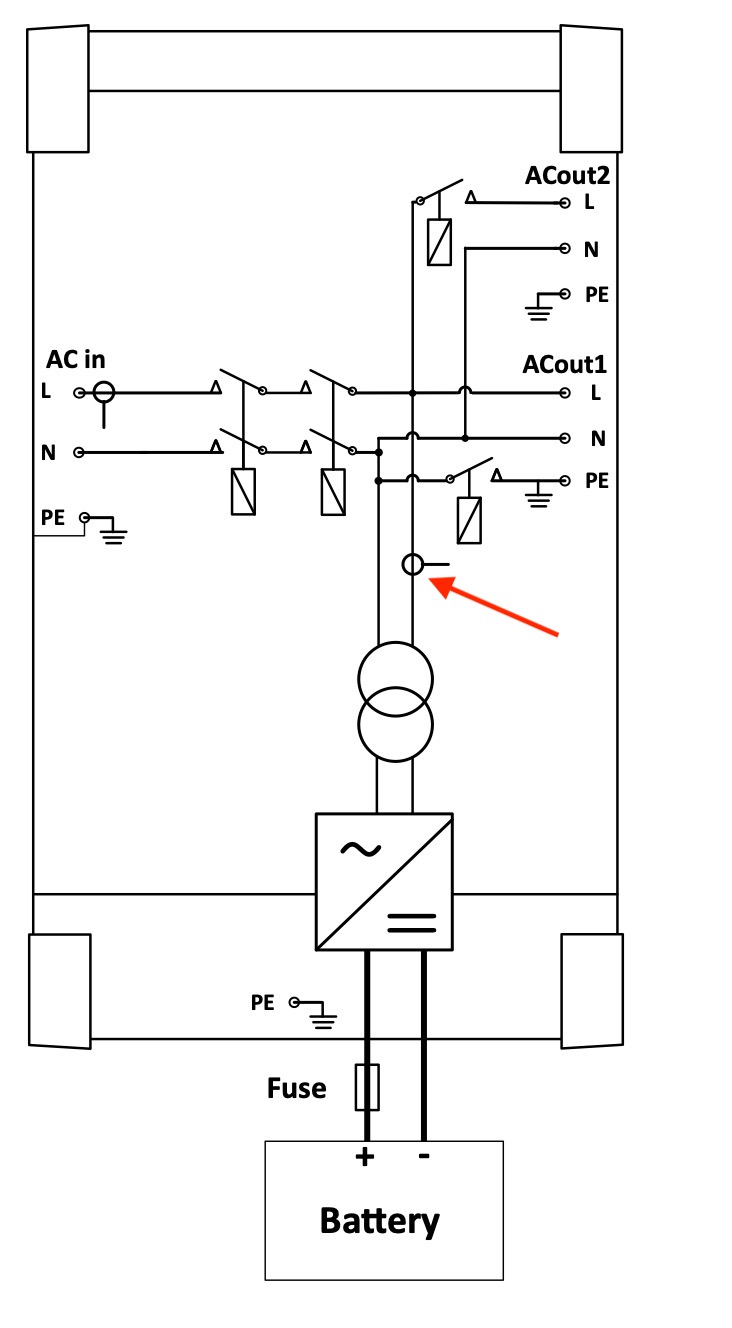
It is not possible to show the power output of ACout1 and ACout2 separately, there is only 1 CT for measurement of this power, as shown below on this diagram with the red arrow:

alt text

If that isn't what you mean, I apologise, perhaps you could draw a diagram of your system and point to where you want to measure the power and it might be clearer for me.


5 comments
2 |3000

Up to 8 attachments (including images) can be used with a maximum of 190.8 MiB each and 286.6 MiB total.

andre avatar image andre commented ·

Thanks for quick response. You are spot on with eloquent diagram to explain!

I misinterpreted the AC Out L 1 as meaning the output L1 whereas it clearly means phase 1 on 3 phase configuration.

I run two independent systems based on the principle that if you have two arms and one fall off there is one left. Like two copies of each chromosome and gene in case one faulty.

My house is supplied by 3 phases but I do not use any 3-phase devices. I use 8 kW Quattro (servicing 2 phases, well-point, water supply & heat-pump on Output 1) and 5 kW Multi (servicing 1 phase, lights, pcs, TV, fridge, chargers, router on Output 1). Also means I have two independent battery banks. I never loose power on critical devices as I can switch supply between two system when one is down.

I am moving to not gird-feeding & not having enormous battery banks and still using all the solar power I make.

Your machines are really brilliant and in my scenario they often run at close to ceiling capacity (I do keep them cool!) with no problems.

Best Wishes
Andre

0 Likes 0 ·
Warwick Bruce Chapman avatar image Warwick Bruce Chapman commented ·

Hello @Guy Stewart (Victron Community Manager) Where did you get this diagram from?

In the printed manuals for the MultiPlus 2 and Quattro the CT is not reflected.

0 Likes 0 ·
Guy Stewart (Victron Community Manager) avatar image Guy Stewart (Victron Community Manager) ♦♦ Warwick Bruce Chapman commented ·

Hi @warwick,

It was a special once off I got from the engineering team.

I was working on a new documentation system for the manuals, so I took the opportunity to write the MultiPlus-II GX manual.

I preferred it, and it was a personal preference. It is publicly available here, in the MultiPlus-II GX manual.

0 Likes 0 ·
Warwick Bruce Chapman avatar image Warwick Bruce Chapman Guy Stewart (Victron Community Manager) ♦♦ commented ·

That looks fantastic! Is that now printed in the booklet that is shipped in the box with the GX?

0 Likes 0 ·
andre avatar image andre Warwick Bruce Chapman commented ·

Hi @Guy Stewart (Victron Community Manager), It would be stylish to replace the diagram on the actual machines with this one!

0 Likes 0 ·