question

ruben avatar image
ruben asked

Solarcharger and it's max PV current (oversizing PV-Array)

Hi Guys, I am new on this forum, but I would love to get some clarification regarding the maximum currents which may flow at the PV-array. I have looked around this forum, but I did not find a proper answer till know, with a clear explanation WHY/ HOW the MPPT is limiting currents...

another discussions around this topic is for instance: smartsolar-maximum-input-current

To be clear, we All know and accept that the Voltage limit (Voc) shall never be higher than the MPPT allows...


The questions comes from the manuals/ Data-sheets which list 2 different footnotes...

@ Manual:

Footnote 2): A higher short circuit current may damage the controller in case of reverse polarity connection of the PV array.

@ Datasheet:

Footnote 2): A PV array with a higher short circuit current may damage the controller"


And generally speaking people tell me that the PV-currents like Isc, may never be able to be higher than the rated current of the Solarcharger at it's PV-side. BUT, if I read the footnotes from both Manual and Data-sheet I get confused, and would like to better understand why Victron is writing this.

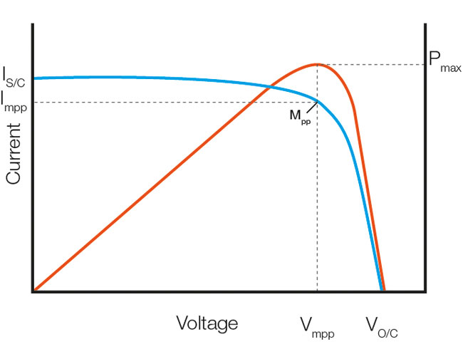
For me are these SolarChargers smart devices which can control Voltage and currents very well. It is for instance possible to lower the charge current by changing it's settings via the app. Why would then oversizing a PV-array (with e.g. a SmartSolar 75/15) with respect to Isc be dangerous for the device? If I would hook 2x 60cell PV-panels in parrallel for instance, theoreticlly a Isc of around 20A could occur.. But to my opinion this Isc Current will never occur within the solarcharger because it is searching for it's MPP. On the other hand Impp could theoretically still be higher than 15Amps, like around 17Amps which would be too high as well. BUT, Is this device not able to limit its input current (in this case max. 15Amps) by deviating from it's MPP working point (like lower it's Amps by increasing the Voltage to Ioc)??


I downloaded version 06 of following Manual https://www.victronenergy.nl/upload/documents/Manual-BlueSolar-charge-controller-MPPT-75-10-75-15--100-15-EN-NL-FR-DE-ES-SE.pdf:

and I download the Datasheet of the same MPPT, Datasheet-Blue-Solar-Charge-Controller-MPPT-75-10,-75-15-&-MPPT-100-15-EN.pdf).


Well looking forward for some comments/ Questions/ answers and/or clarifications :)

Ruben


current limit
1576534740338.png (82.0 KiB)
2 comments
2 |3000

Up to 8 attachments (including images) can be used with a maximum of 190.8 MiB each and 286.6 MiB total.

klim8skeptic avatar image klim8skeptic โ™ฆ commented ยท

Most likely the protection device is only rated to handle 15a, in the case of pv reverse polarity connection.

0 Likes 0 ยท
ruben avatar image ruben klim8skeptic โ™ฆ commented ยท

Yes I agree, I think that as well in case of 'reverse polarity'. Thanks for the comment :)

0 Likes 0 ยท
1 Answer
JohnC avatar image
JohnC answered ยท

Hi Ruben. My understanding (not official Victron-speak)..

The mppt does not directly control Amps on the pv input. That comes as a consequence of the Vmp it's targetting, or when throttling V may rise close to Voc. Your 75/15 has a hardware-set limit of 15A into Vbat, and as panel V is always higher under production, the panel current will always be less than 15A.

The Isc limit is perhaps more a safety thing related to faults. Reverse polarity could be called an externally-applied fault. And you've seen Lucian suggest mosfet damage too.

Other faults might be in manufacturing (heaven forbid), some critter squeezing in, or even installer abuse (dropping it?), leading to a short-circuit across the pv input terminals. Isc then applies, and if far greater than the pcb has been designed and tested (hopefully) for, may mean the difference between a little smoke/melted plastic - or something more spectacular, like blowing itself off the wall, or a fire.

In reality, observing the Voc and Isc limits whilst still maintaining a substantial ability to 'overclock' pv capacity, shouldn't be an issue for most users.


1 comment
2 |3000

Up to 8 attachments (including images) can be used with a maximum of 190.8 MiB each and 286.6 MiB total.

ruben avatar image ruben commented ยท

Hi @JohnC, many thanks for your answer. Sounds quite logic what you are saying, thanks for giving those examples. That helps imagining what could create a Short-circuits and consequently what could happen...

you write: "Your 75/15 has a hardware-set limit of 15A into Vbat, and as panel V is always higher under production, the panel current will always be less than 15A." --> True, and that confirms indeed what I was expecting too.

Just some detailed question (maybe @Lucian Popescu (Victron Energy Staff) likes to answer that as well). I am not totally aware of how this 'current-limiter'at Vbat is working, but in case of a PWM system, you could say that short Current peaks could occur, keeping RMS currents still to a certain maximum amperage (lets say 15Amps for a MPPT 75/15 for instance). Could that be the reason, that the MOSFETS are getting challenged for working at high(er) currents, which will reach it's limit at some point?


"...may mean the difference between a little smoke/melted plastic - or something more spectacular, like blowing itself off the wall, or a fire." --> True, you always need to design within some limits and to take care of the overall safety.


thanks again,

Ruben


0 Likes 0 ยท

Related Resources

Additional resources still need to be added for this topic