question

shaunuk avatar image
shaunuk asked

Cerbo vrm and beta ui all showing different and wrong data when using solar assistant

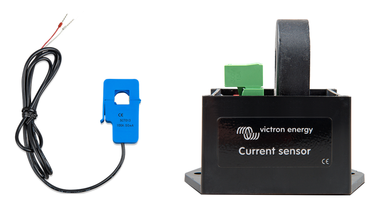
I have two systems, out of about 30 where a second ct has been added to monitor a third party ac coupled solar inverter. This should work, and it kind of is working, but all the UI's show strange information.

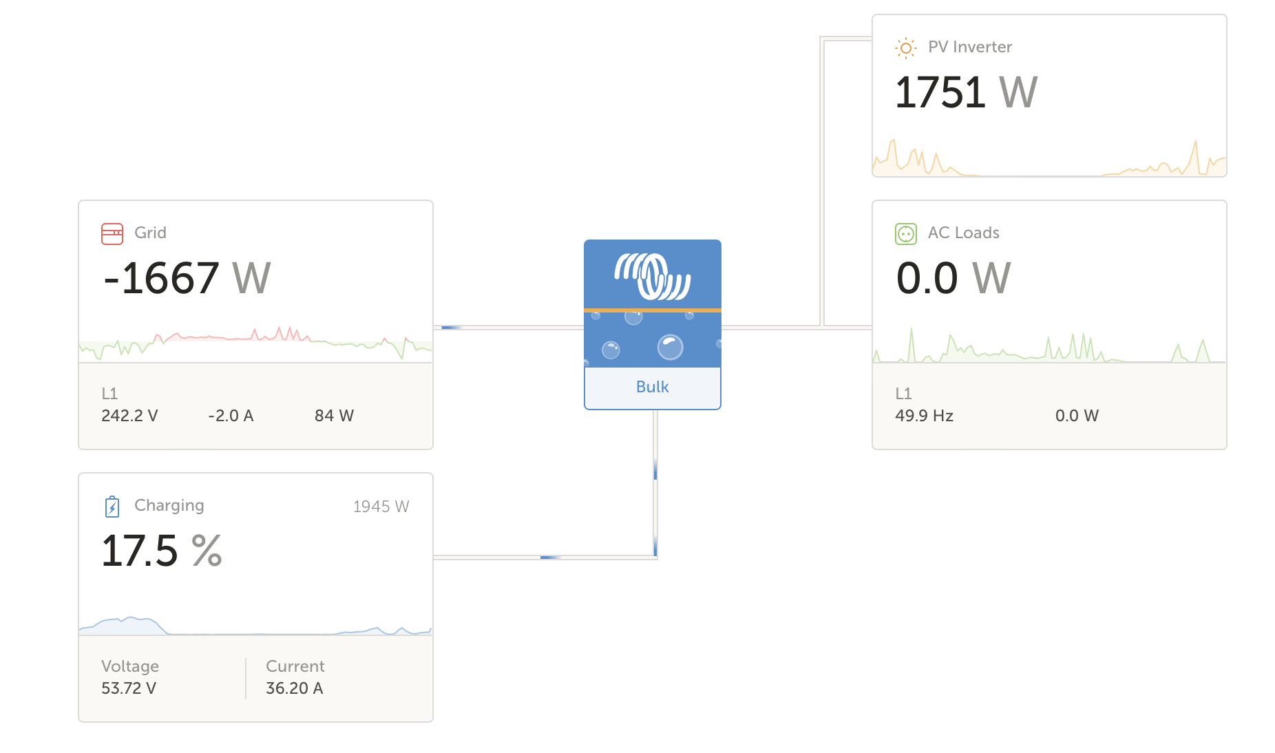
When the solar ct (on aux2) is unplugged the system works as a normal ESS and does indeed store excess PV energy in the battery, but when the ct is connected, ac loads seem to show as 0 or some other figure, sometimes a few hundred watts - also wrong, and the solar generation shows as going to the grid. Even though a second check on the grid shows no current.

That's on the vrm which is wrong and is consistent with the remote console on the GX devices. Ive tried latest firmware's, switching from aux 1 to aux2, i've tried beta firmwares.

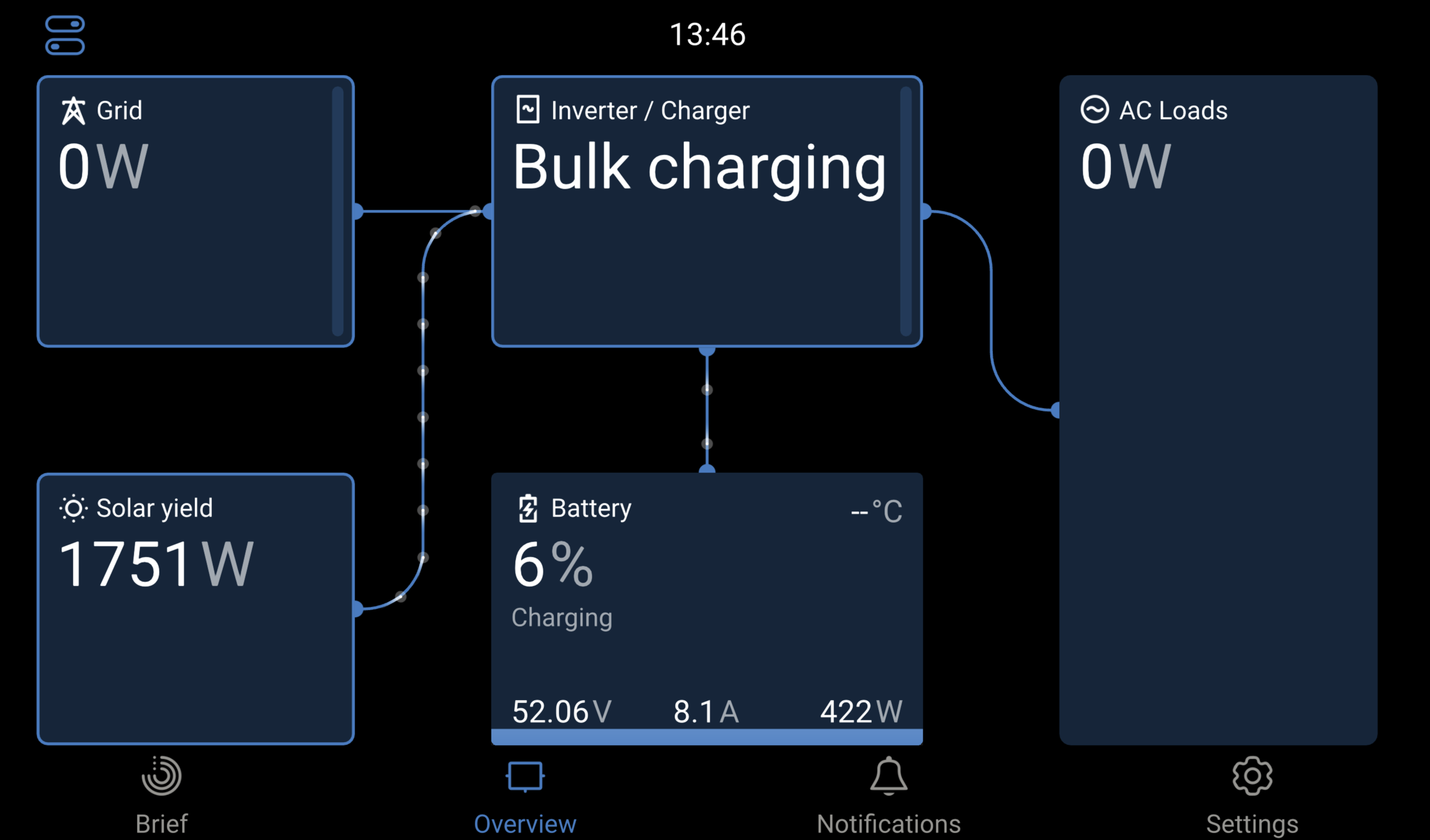
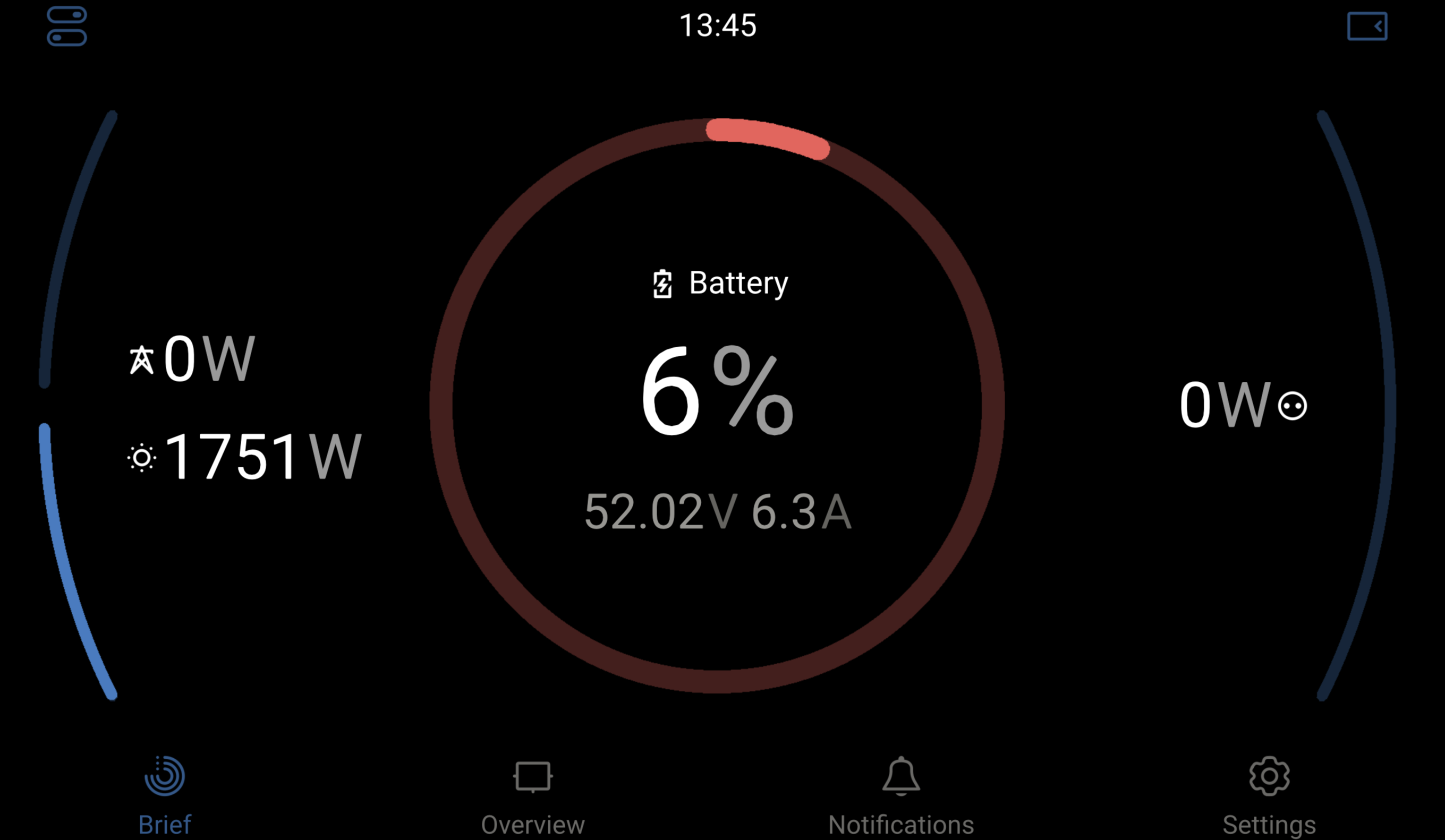
Then as a last resort I looked at the GUI-V2 on vrm and it's almost right. The grid shows as 0, the battery shows as charging during the day, the only thing missing is the loads are wrong.

I really hope someone can tell me what's wrong, even if it's just a reversed ct, both systems have the grid ct arrows pointing towards the load (away from the grid). Both work fine when the solar ct is disconnected. In fact they actually work fine with it connected, but the UI is all wrong.

Whats going on ?

Brand new 2024 multiplus 3k and a multiplus 8k on different systems, latest firmware's all arround.

Check these screenshots from the same time

screenshot-2024-07-07-at-134614.pngscreenshot-2024-07-07-at-134601.pngscreenshot-2024-07-07-at-140638.png

Multiplus-IIVRMsolarbeta
2 |3000

Up to 8 attachments (including images) can be used with a maximum of 190.8 MiB each and 286.6 MiB total.

4 Answers
nickdb avatar image
nickdb answered ·

I wouldn't bring gui beta into the topic as it is in beta and questions about that need to be contained in the venus beta topics, not on general Q&A. It will just confuse things as will hopping between official and beta software.

Pick a stable base and focus on that.

2 |3000

Up to 8 attachments (including images) can be used with a maximum of 190.8 MiB each and 286.6 MiB total.

ejrossouw avatar image
ejrossouw answered ·

@Shaunuk Firstly you are on the beta firmware and this question therefore will be best served in the modifications space under the new gui section. Otherwise,If you have system of the same configuration but only two with this problem. What is different between them, other than the obvious possibility of beta version? Also you mention CT which has a dedicated current sense port for it. Are you referring to the AC sensor?

2 |3000

Up to 8 attachments (including images) can be used with a maximum of 190.8 MiB each and 286.6 MiB total.

shaunuk avatar image
shaunuk answered ·

Hi, thanks for the questions. I will clear up the points.

I tried the beta firmware as a last resort, and it has confirmed some suspicions. I have about 30 systems running live, only two of them have secondary CT clamps for monitoring third party ac coupled solar and both have this trouble not being able to use or trust any of the data on the dashboards.

The two systems in question have a CT attached to the current sense port for grid monitoring, they also have a second ct connected to monitor ac coupled solar, ive tried temp sense, aux1 and aux2 on both systems. All have the same incorrect monitoring.

My guess is the second ct is some how being used to calculate apparent grid export/import when it should only be for solar, (solar assistant as well as ESS helpers are installed) as its blinding the system to ac consumption in the house and also reporting almost identical ac export to the grid thats being generated in the solar pv inverter.

This is concerning for the customer (end user) as they cant trust the dashboards, and depending on which they look at they get different figures.

End Result, the system and ESS is working, but the data is completely wrong and also conflicts depending on what dashboard you look at. Unplugging the solar ct on aux2 returns the system to normal reporting.


3 comments
2 |3000

Up to 8 attachments (including images) can be used with a maximum of 190.8 MiB each and 286.6 MiB total.

nickdb avatar image nickdb ♦♦ commented ·

Can you confirm which specific clamp you're using and where exactly it is connected?

I may be wrong, but under the impression you either need to use an EM or this one if you want to use it to measure PV.

https://www.victronenergy.com/live/ac_current_sensor:start


0 Likes 0 ·
Alexandra avatar image Alexandra ♦ nickdb ♦♦ commented ·

Small side note, even the battery percentage is not close 6% vs 17%?

Is the AC PV position before or after the inverter?

0 Likes 0 ·
ejrossouw avatar image ejrossouw commented ·

CT on left which has a dedicated current sensor port on the MP and basically disconnects the MP internal sensor and moves it externally to measure the grid. There is also a setting in VE.config to reflect this.

Never used it personally, but the AC sensor right is connected to AUX to typically measure AC coupled PV and also has an assistant. This is typically done in other ways with e.g. 2 x ET112 or ET340 etc.

1720367454460.png

0 Likes 0 ·
1720367454460.png (242.1 KiB)
shaunuk avatar image
shaunuk answered ·

ah yes, so I have the one on the left connected for grid monitoring into the normal grid ct input, and that works great, as usually until the solar ct is connected, which is the one on the right with the correct pins set for our solar system size, thats connected to aux2 with solar assistant configured for aux2, ive tried aux1 and temp inputs as well

2 |3000

Up to 8 attachments (including images) can be used with a maximum of 190.8 MiB each and 286.6 MiB total.