question

hoop24 avatar image
hoop24 asked

Testing 7KW isolation Transformer is functioning correctly

Hello,

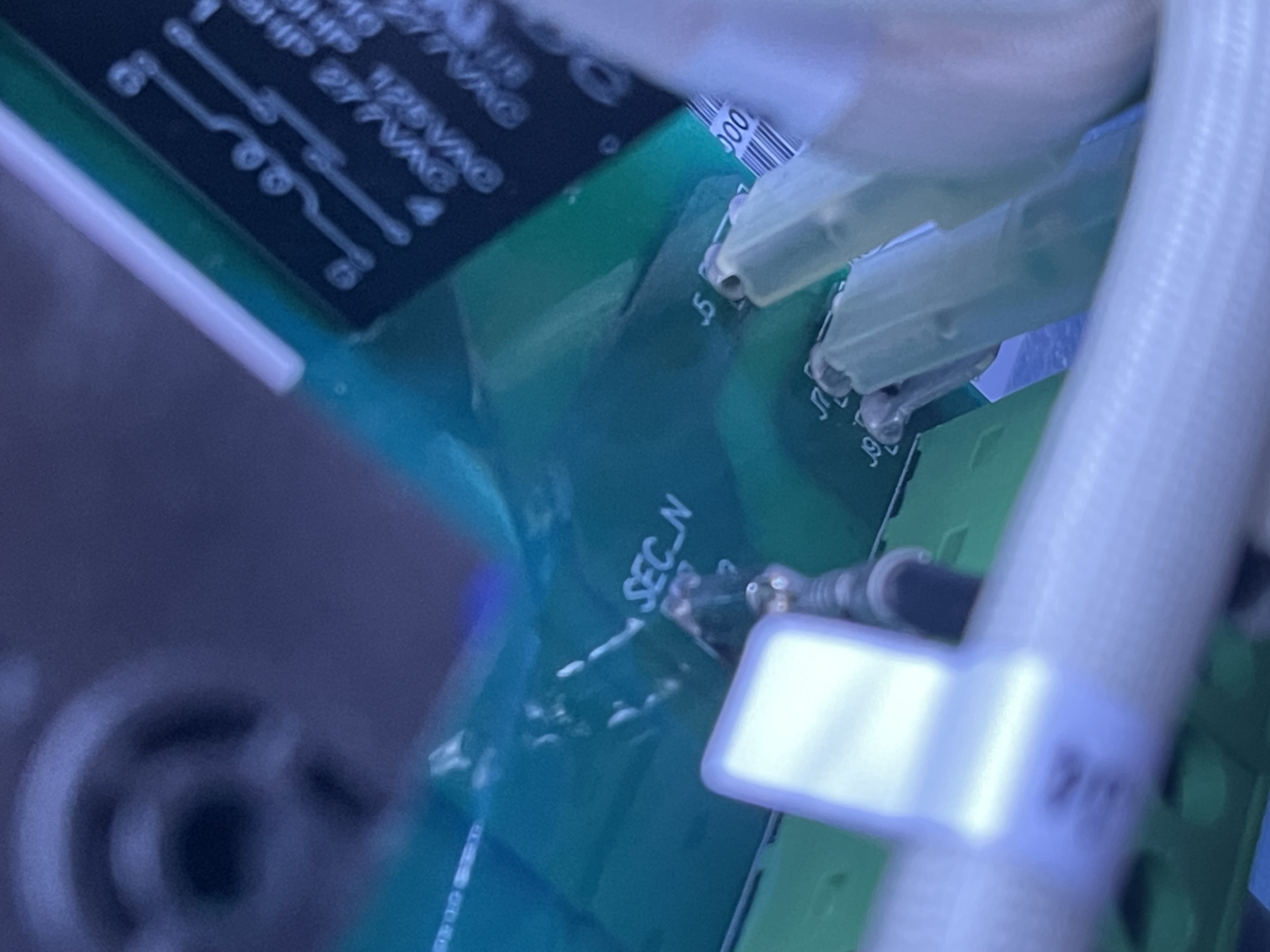
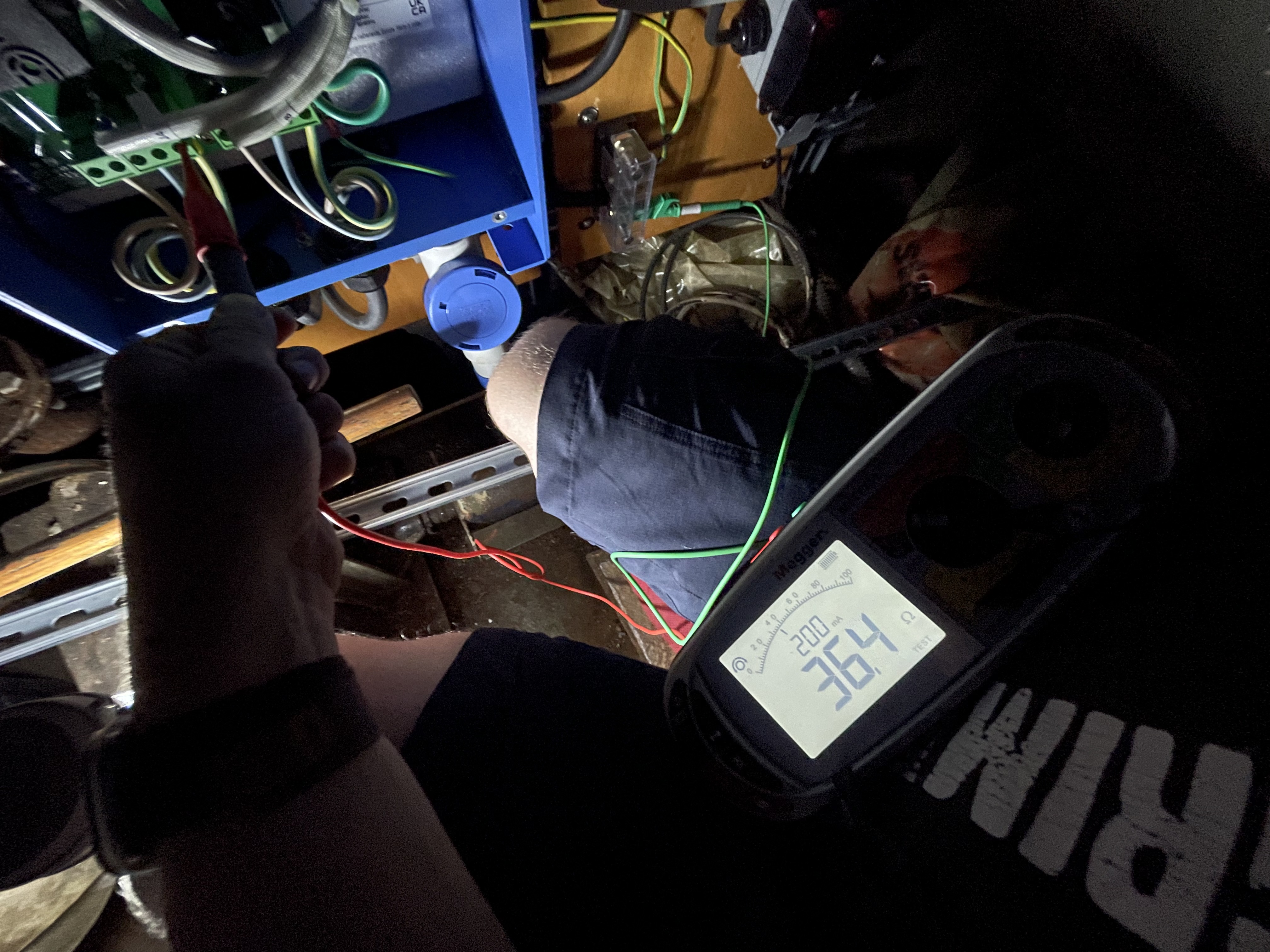
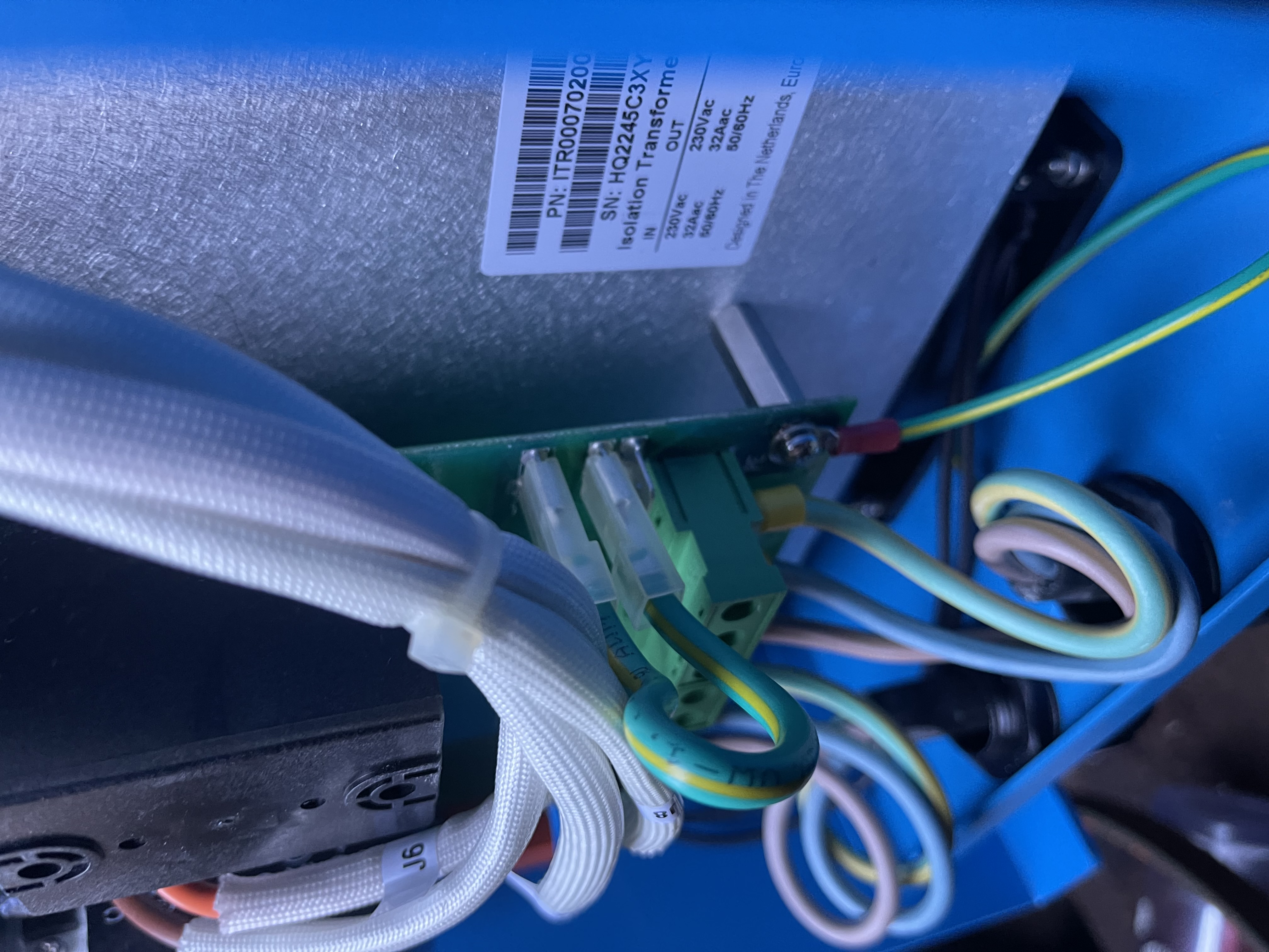
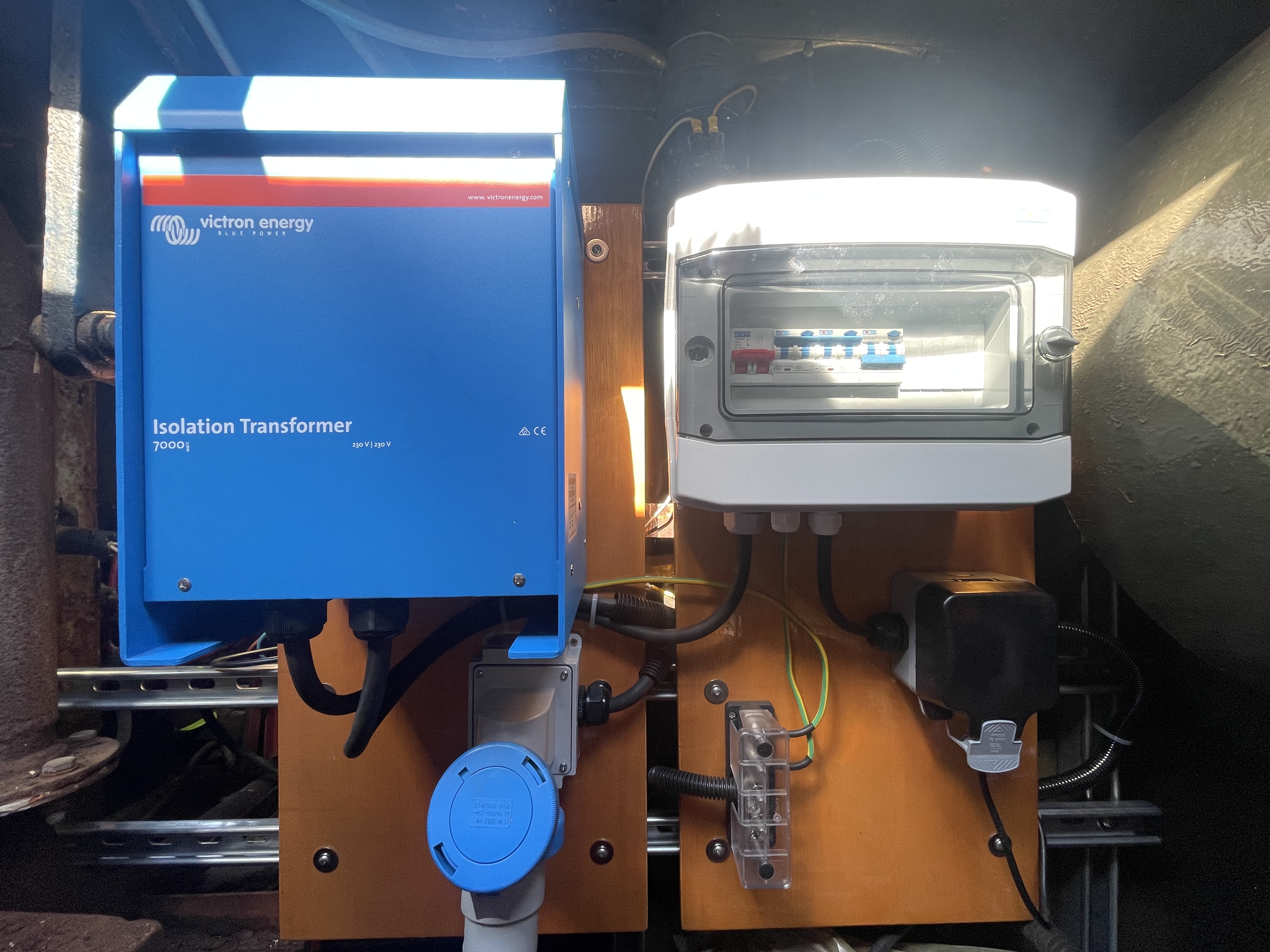
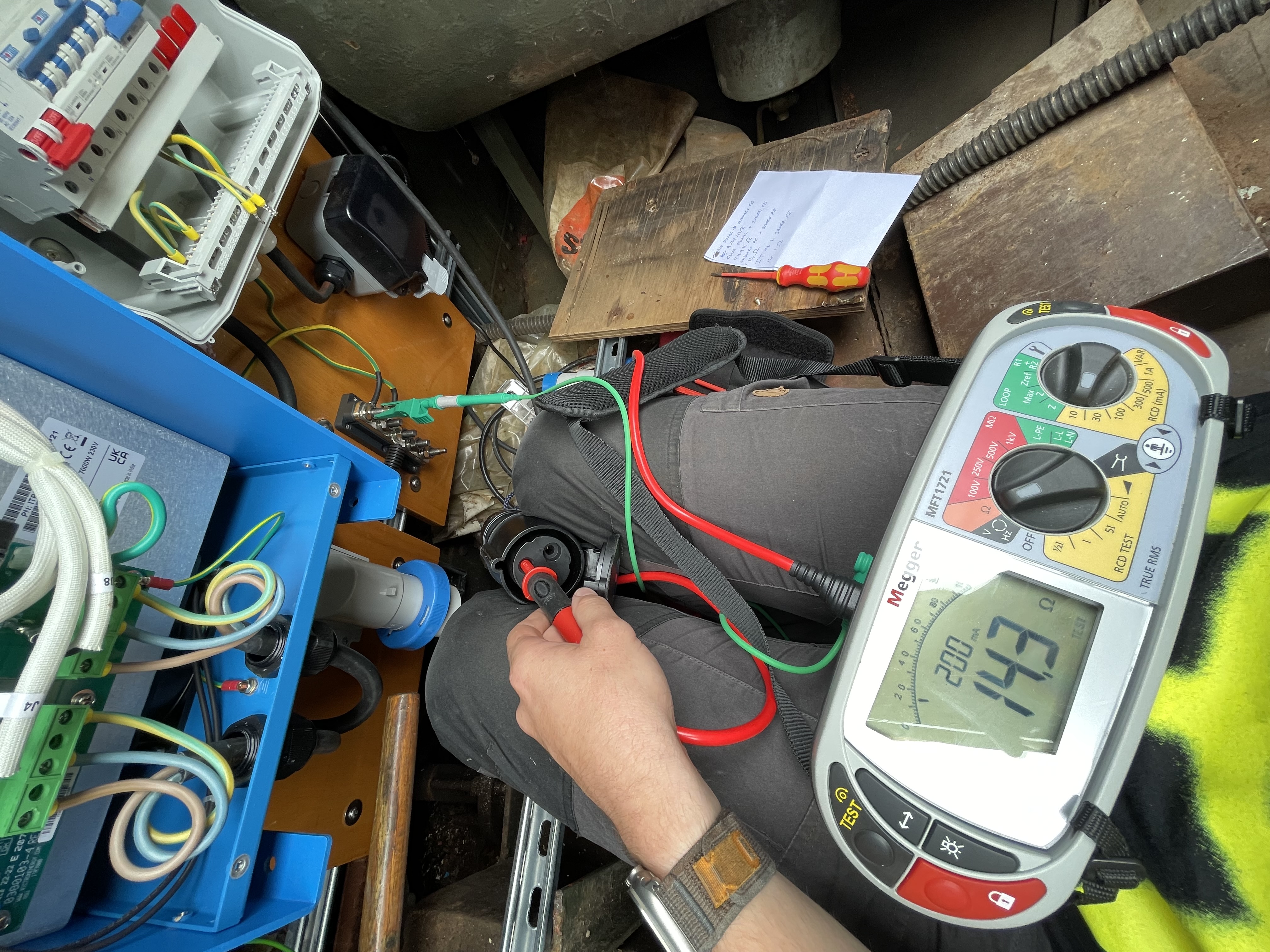
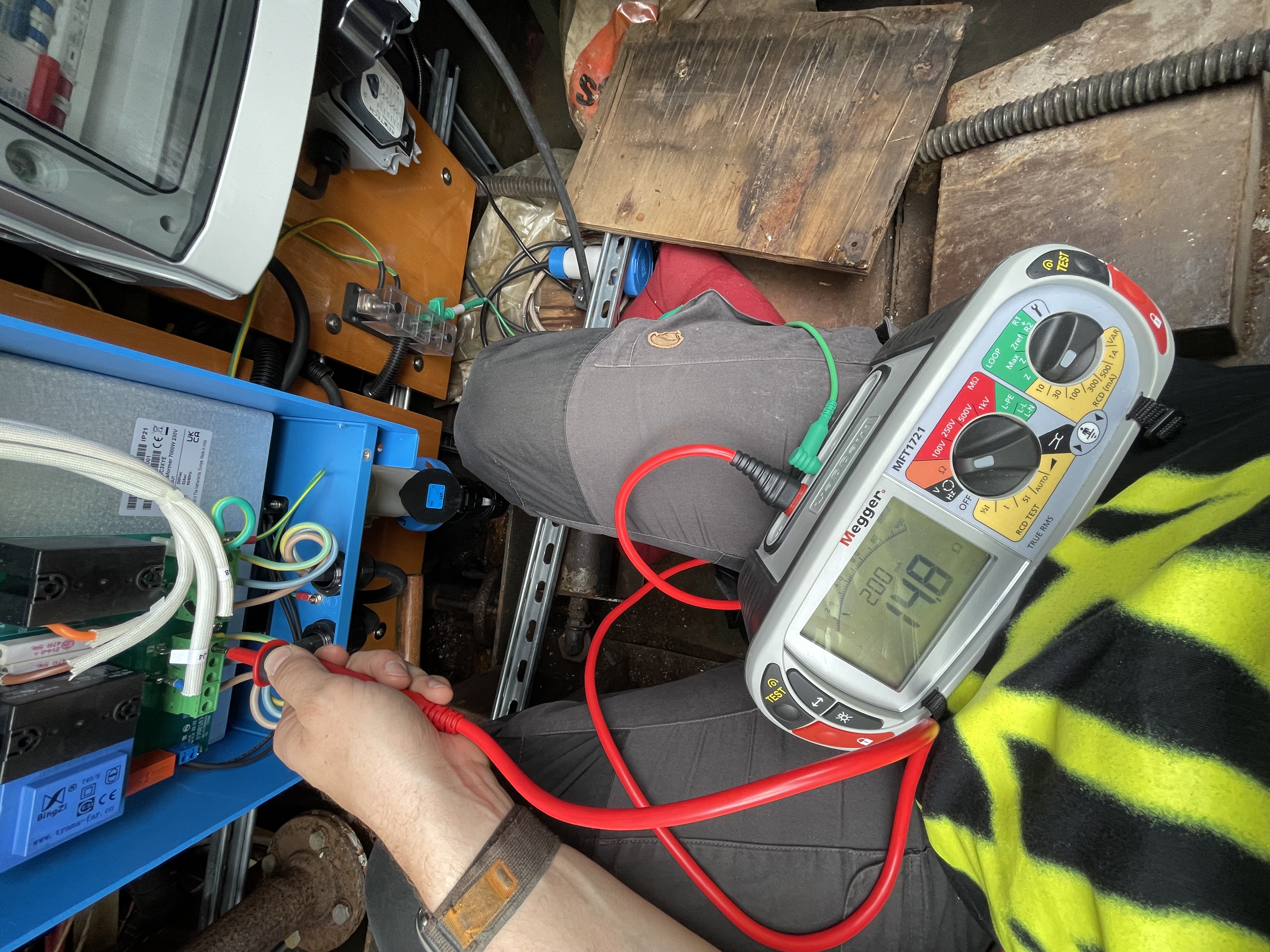
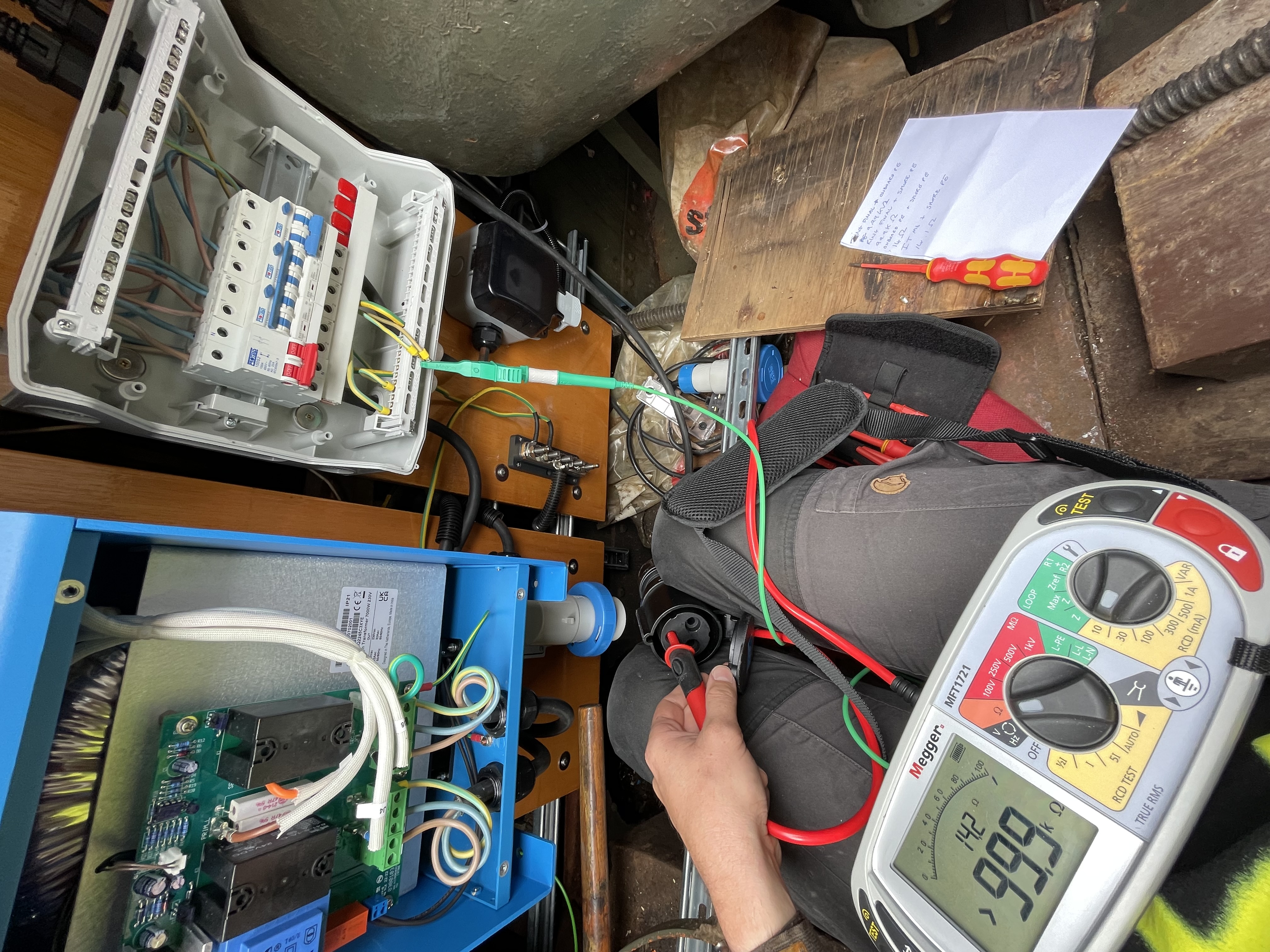
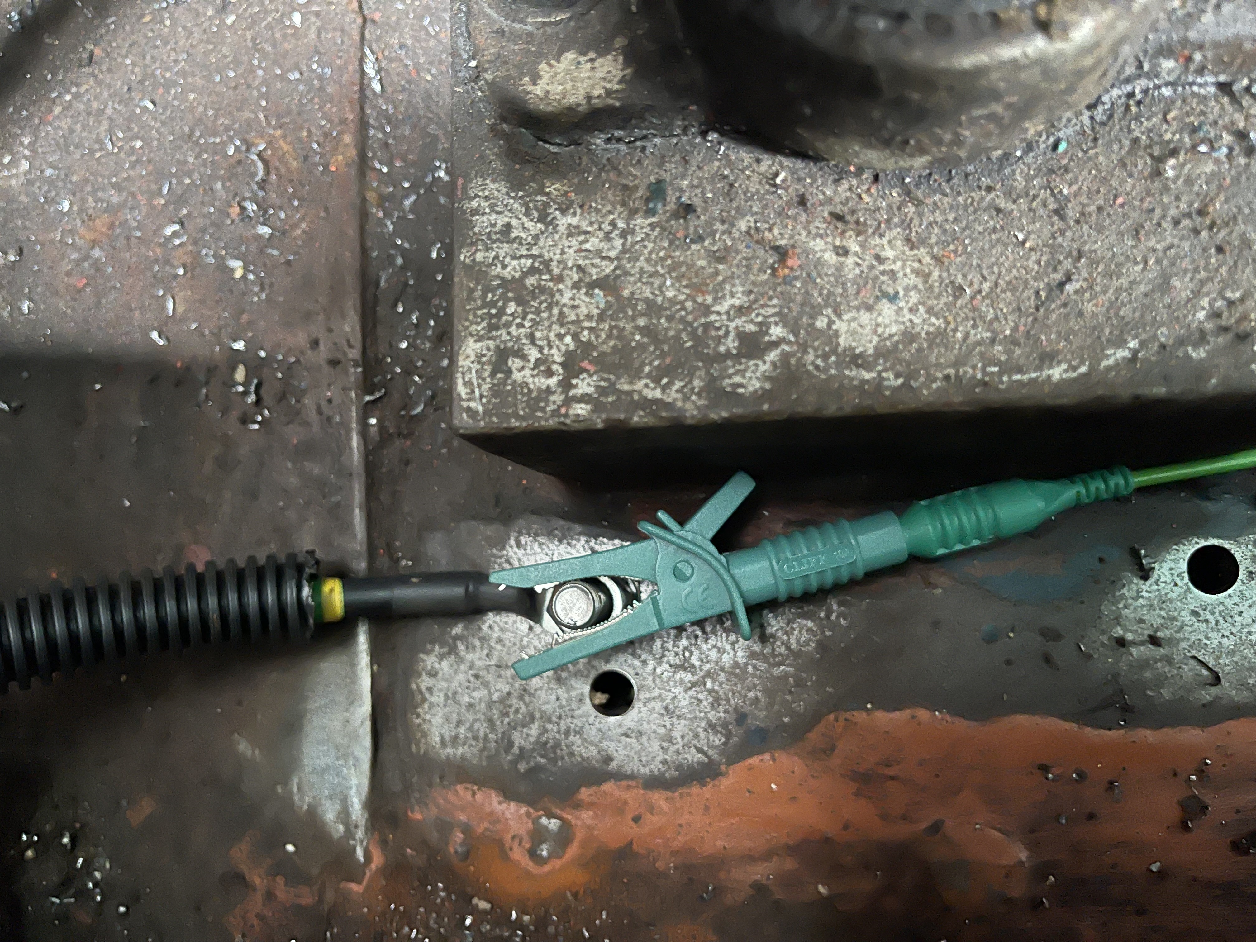
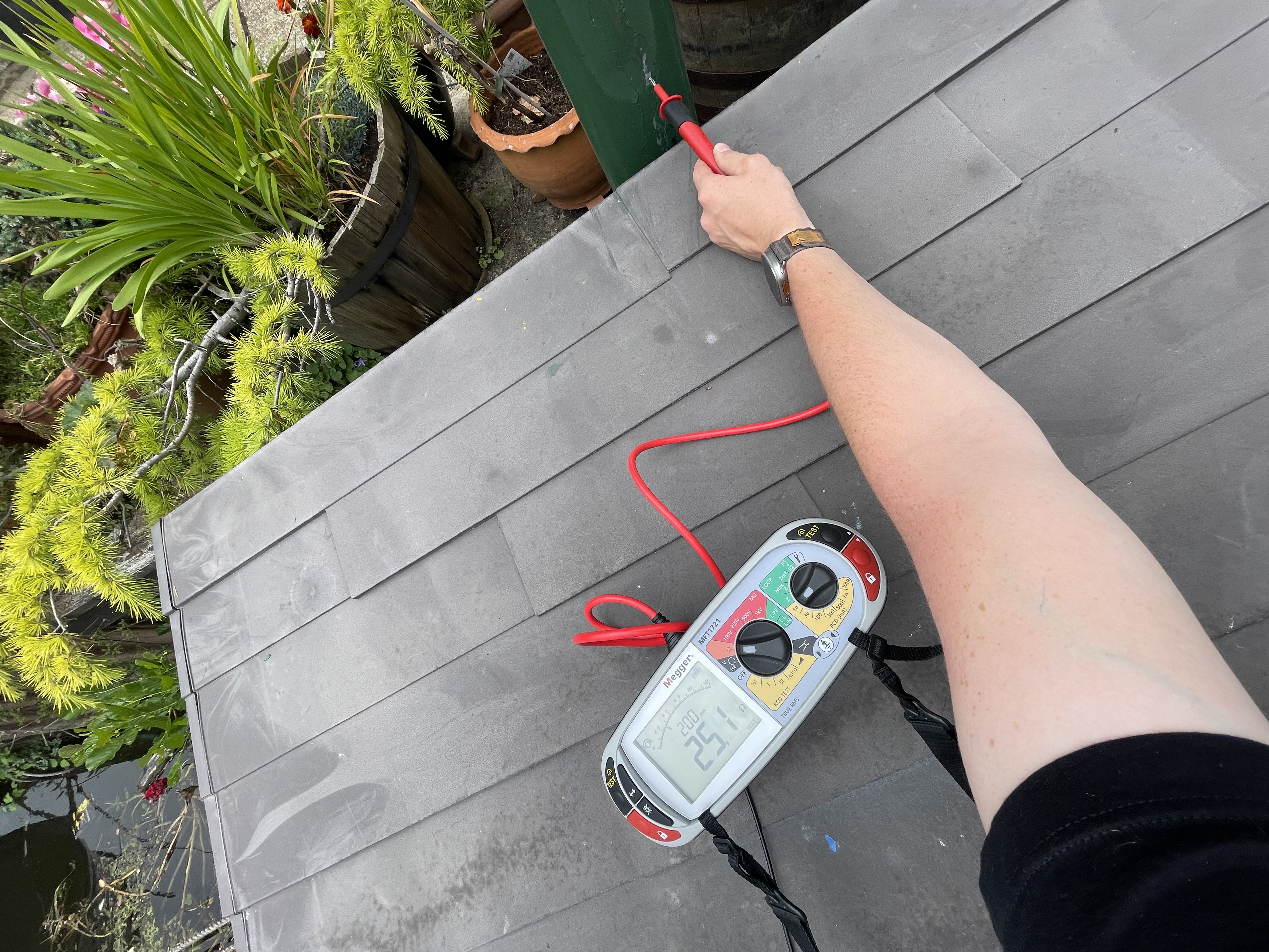
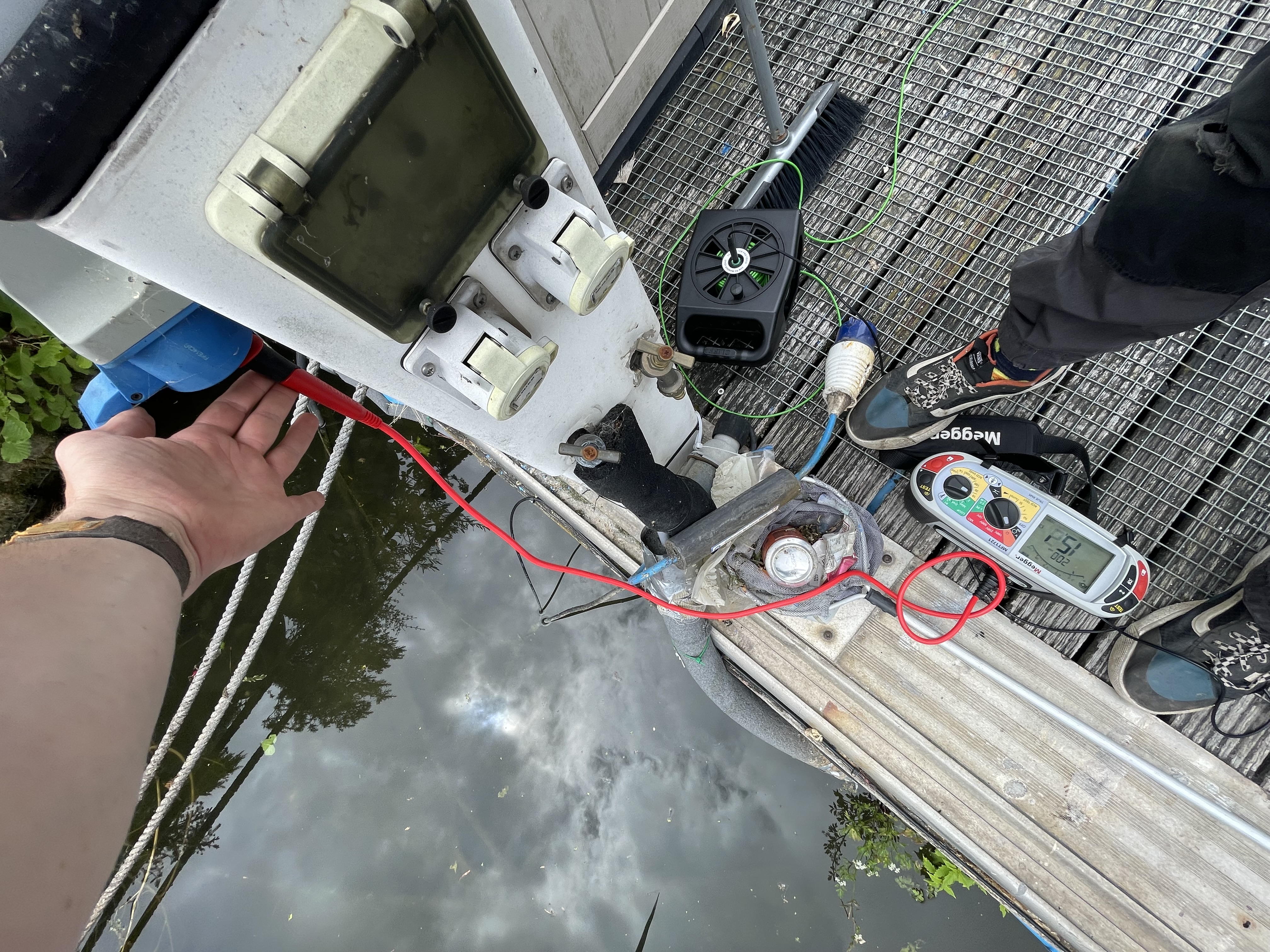
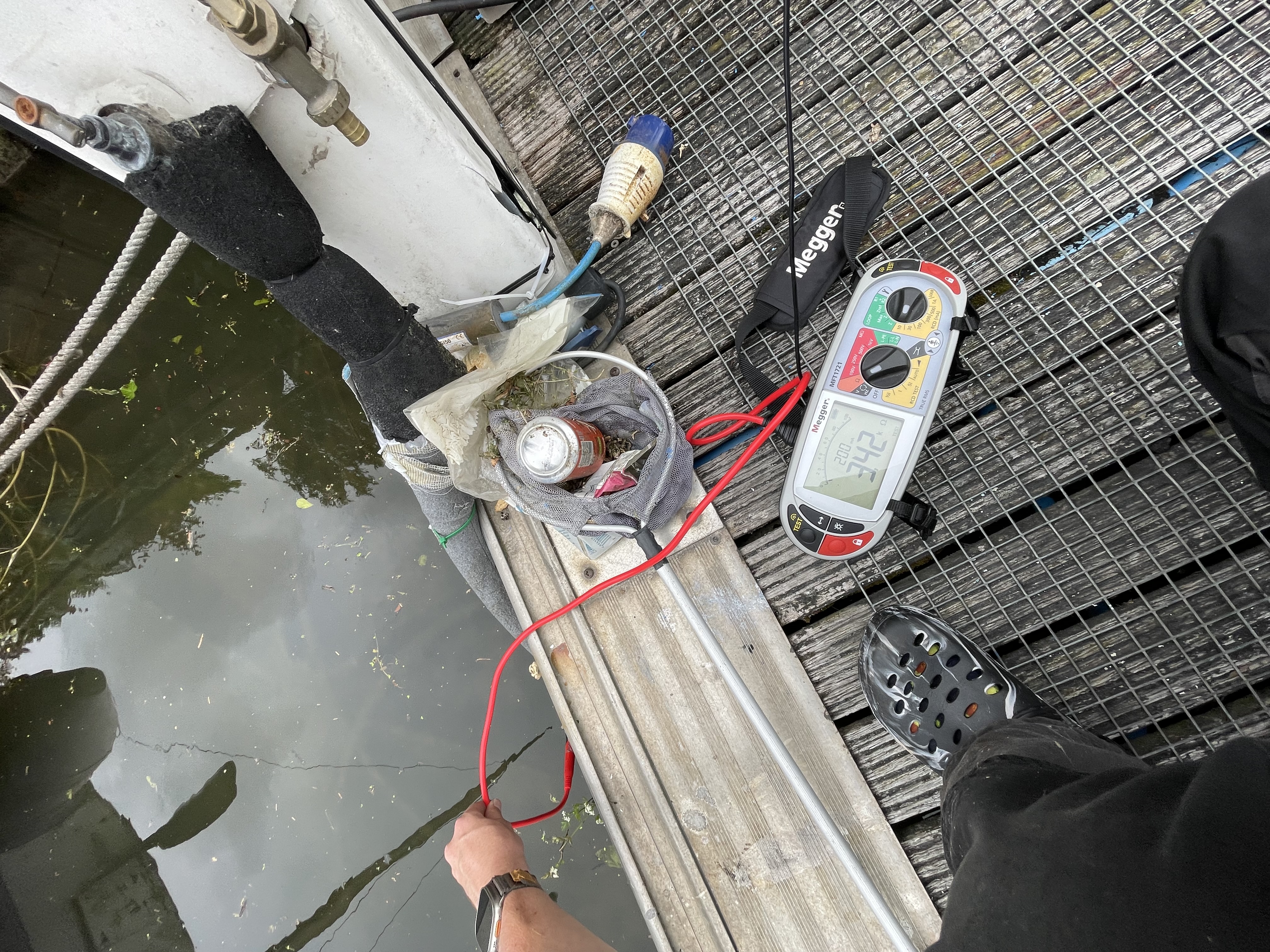
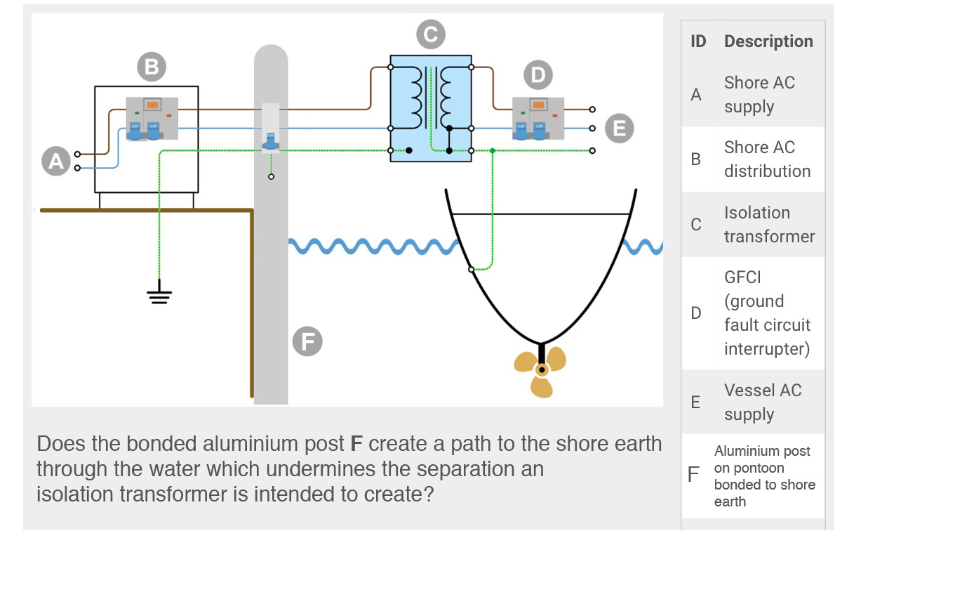
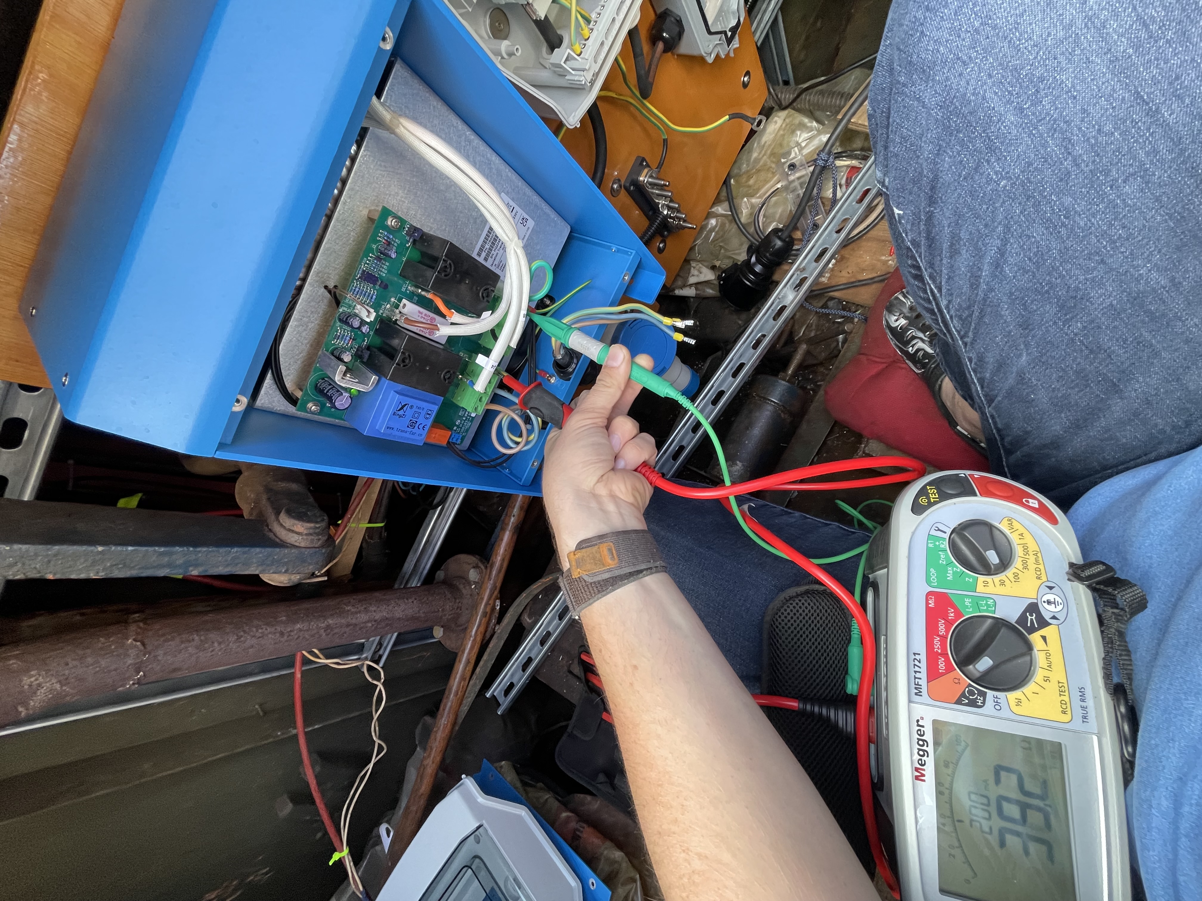
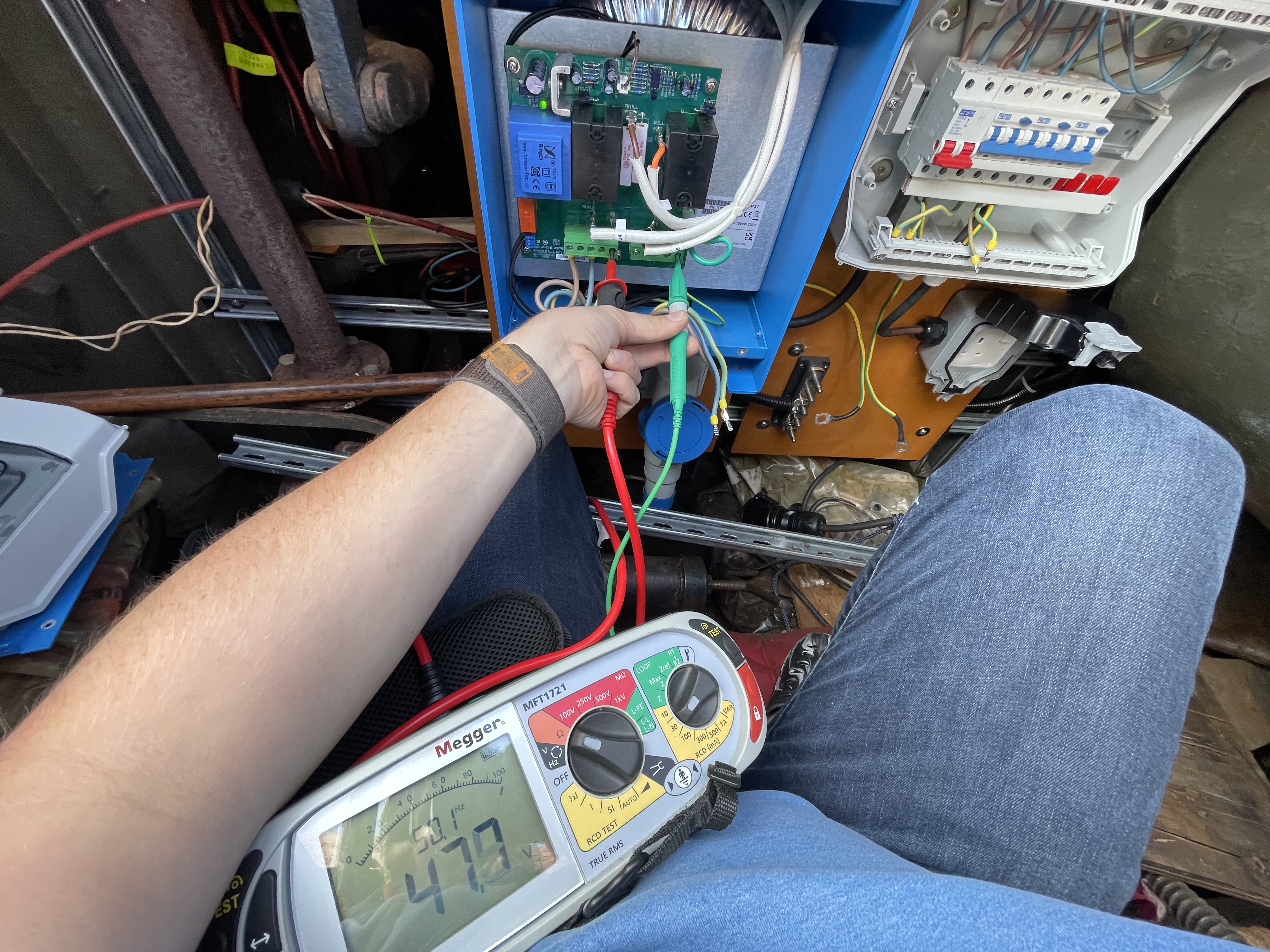
I have just fitted a Victron 7KW Isolation Transformer on my barge which has a metal hull. I tested for continuity between the two earths to test for the desired separation and got a reading of only 36.4 ohms (see photo attached). Jumper cable on the output side is fitted to J5-J7 spade connectors, casing earth is then bonding to a busbar which is then bonded to the hull by the engine mounting point. I would have expected either a complete open circuit reading or a high ohms reading. Do I have a problem somewhere with an alternate path to shore earth? What tests should I be carrying out and what readings should I expect to see?

Thanks,


Joe.

img-3792.jpeg

img-4014.jpeg

img-3790.jpeg

img-3821.jpeg

Isolation Tranformermarineisolation
img-4014.jpeg (2.2 MiB)
img-3792.jpeg (1.4 MiB)
img-3790.jpeg (2.0 MiB)
img-3821.jpeg (2.8 MiB)
2 |3000

Up to 8 attachments (including images) can be used with a maximum of 190.8 MiB each and 286.6 MiB total.

18 Answers
cardy01 avatar image
cardy01 answered ·

Hi

I'm in agreement with you that 36.4 ohms is too low for an open circuit and too high for a short or deliberate connection.

Question: the yellow/green wire coming out of your consumer unit - is that the PE for the consumer unit? If so why doesn't that come from the secondary of the IT?

What's in your shore power socket - is there a chance you have a "fortuitous earth" in there? Maybe something in contact with the ?metal? back plate?

Is there evidence of chafing where the shore power cable enters the boat?


2 |3000

Up to 8 attachments (including images) can be used with a maximum of 190.8 MiB each and 286.6 MiB total.

hoop24 avatar image
hoop24 answered ·

Hello,

So the the green wire coming from the CU is attached to the busbar that the IT is connected to as well as my hull bond by the engine mounts. Both are attached to output side of the IT (IT Casing and CU).

Do you mean the earth on the shore or my Ceeform inlet on the boat? In the boat everything is in flexi or plastic components. If you mean the shore earth what should I bring looking for?

So in order for me to be getting this reading it’s either the IT isn’t working or my boat is somehow connected to shore earth somehow through the water or a faulty shore cable?

2 |3000

Up to 8 attachments (including images) can be used with a maximum of 190.8 MiB each and 286.6 MiB total.

cardy01 avatar image
cardy01 answered ·

The purpose of the jumper between J5 and J7 is to bond the neutral to "earth" at the output of the IT (to ensure your RCDs operate) I don't see why you would also add a PE between your busbar and the CU since it should come from the IT? What happens to the reading with the busbar CU connection removed?

I would also look for damage to your shore power lead. Try substitution?

2 |3000

Up to 8 attachments (including images) can be used with a maximum of 190.8 MiB each and 286.6 MiB total.

hoop24 avatar image
hoop24 answered ·

Yes I will try a substitute cable, Would this be caused by a break in the cable that’s travels through the water? Or a break in the cable onboard the boat somewhere making contact for the IT? That is essentially what I’m looking for isn’t it a connection for the IT.

I will also try a test with this CU earth.

Even with no alternate connections to shore earth what readings should I expect as I can only imagine is wouldn’t be an open connection because you are floating above the Shore ground essentially with the water as a barrier.

2 |3000

Up to 8 attachments (including images) can be used with a maximum of 190.8 MiB each and 286.6 MiB total.

cardy01 avatar image
cardy01 answered ·

The purpose of the isolation transformer is to ensure that there is no physical path from the live/neutral and PE connections between the shore and the boat - so you should see an open circuit value.

Your reading indicates there is a parallel path from shore to the boat for at least the PE connection.

It's also possible there is a problem with the IT but I would check the wiring first.

The green/yellow wire that goes to one of the PCB mounting screws - is that something you added?

Your case connection to your busbar should use the M6 stud/nut between the 2 cable glands ....

2 |3000

Up to 8 attachments (including images) can be used with a maximum of 190.8 MiB each and 286.6 MiB total.

hoop24 avatar image
hoop24 answered ·

I added the earth from the CU to the busbar I added and yes I used the M6 stud between the glands to ground the case within the boats earthing system.

The earth from the PCB I didn’t add it came this way and the manual doesn’t mention anything about it besides in the box your given a spare cable.

Could it be that one end in my boat is in the mud slightly? Grounding it that way?

2 |3000

Up to 8 attachments (including images) can be used with a maximum of 190.8 MiB each and 286.6 MiB total.

cardy01 avatar image
cardy01 answered ·

I imagine your barge is blacked below the waterline ..... I don't think your issue is grounding of the hull by water or mud ..... my IT is open circuit except when the "spare" cable is connected when the boat is on dry land.

2 |3000

Up to 8 attachments (including images) can be used with a maximum of 190.8 MiB each and 286.6 MiB total.

hoop24 avatar image
hoop24 answered ·

Would the shore cable being in the water for some of its journey to shore outlet be the potential issue? if it’s got a break in it?


Is that something you could take a picture of potentially? Your system I mean?


But in terms of protection right now with a reading like this, only in a fault scenario would I be experiencing any galvanic corrosion?

2 |3000

Up to 8 attachments (including images) can be used with a maximum of 190.8 MiB each and 286.6 MiB total.

cardy01 avatar image
cardy01 answered ·

If the shore cable is faulty then mulitple things could be going on .... it would be better not in the water even if it's healthy.

My system looks similar to yours - incoming shore power lead to socket - socket to IT - IT to consumer unit - with appropriate breakers at each point. But sorry I can't dismantle the sofas to take pictures.

Galvanic corrosion is a complex subject but since the purpose of the IT is physical separation of shore and boat wiring I'd suggest you have a problem that needs fixing.

If you pull the shore power plug does the reading change between left-hand PE connection and your busbar?

2 |3000

Up to 8 attachments (including images) can be used with a maximum of 190.8 MiB each and 286.6 MiB total.

hoop24 avatar image
hoop24 answered ·

I’m away from my boat at the moment but tomorrow I’ll conduct these tests.

2 |3000

Up to 8 attachments (including images) can be used with a maximum of 190.8 MiB each and 286.6 MiB total.

hoop24 avatar image
hoop24 answered ·

Ok, so I’ve done some testing today. I think I have another issue.

With the shore power disconnected onboard my boat, testing between the Ceeform earth pin (Shore) and my onboard earthing point to the hull I get an ohms reading of 14.3 ohms. So my hull is in contact with the shore earth… And I get the same reading when connected through the transformer when it’s on. I tried this with 2 shore cables and one is completely out of the water.

What happening here if the boat earth is getting a resistance reading to shore earth without the shore lead even connected…

The earth from my ring circuit are completely open circuit from my hull earthing pointing as is the neutral and line. I believe that tells me it’s not faulty wiring?


img-4062.jpeg

img-4071.jpeg

img-4061.jpeg


img-4062.jpeg (3.2 MiB)
img-4071.jpeg (3.1 MiB)
img-4061.jpeg (3.3 MiB)
4 comments
2 |3000

Up to 8 attachments (including images) can be used with a maximum of 190.8 MiB each and 286.6 MiB total.

cardy01 avatar image cardy01 commented ·
Do you have another shore connection point somewhere?

What mooring lines do you have? Rope, chain, wire hawser?

0 Likes 0 ·
cardy01 avatar image cardy01 cardy01 commented ·

"The earth from my ring circuit are completely open circuit from my hull earthing pointing as is the neutral and line. I believe that tells me it’s not faulty wiring?"

Could you clarify that?

Your 240v onboard earth and neutral should be 0 ohms to the busbar .....

-1 Like -1 ·
hoop24 avatar image hoop24 cardy01 commented ·
They are all rope.
0 Likes 0 ·
hoop24 avatar image hoop24 cardy01 commented ·

What I meant was I don’t have any earth continuity between my disconnected shore cables Earth pin and my ring circuits PE so they are not in contact with the hull anywhere in the installation. Correct?


So what does it mean if I am getting 14.3 ohms of resistance between the disconnected shore cable Earth and the onboard AC Hull bonding point knowing that my ring PE conductors aren’t touching the hull anywhere? There is another connection somewhere through the water? The readings are the same if the shore cable in plugged in and the transformer is on as you can see in the above photos, testing between the input side PE and the output side PE.


Also to test attached a long lead to my hull bond and took it to the shore to test resistance between the pontoon and the pillars the slide up and down on. I got a low reading there also. See attached below. Same as when the shore cable is connected or disconnected. I also got the hell of it out one probe in the water and got a high k-ohms reading. Does this prove anything? Very lost.


Joe.

img-4080.jpeg

img-4077.jpeg

img-4074.jpeg

img-4079.jpeg

img-4069.jpeg


0 Likes 0 ·
img-4080.jpeg (3.2 MiB)
img-4077.jpeg (3.7 MiB)
img-4074.jpeg (4.6 MiB)
img-4079.jpeg (4.2 MiB)
img-4069.jpeg (4.5 MiB)
cardy01 avatar image
cardy01 answered ·

There is something metallic connecting your hull to the pontoon.

Do you have a steel or aluminium passerelle/gangplank?

2 |3000

Up to 8 attachments (including images) can be used with a maximum of 190.8 MiB each and 286.6 MiB total.

hoop24 avatar image
hoop24 answered ·

Not to my knowledge no. Could this be a connection through a neighbouring boat? Not sure what else it could be?

1 comment
2 |3000

Up to 8 attachments (including images) can be used with a maximum of 190.8 MiB each and 286.6 MiB total.

cardy01 avatar image cardy01 commented ·

Good luck hunting it down .... check that removing the gangway doesn't solve it

0 Likes 0 ·
Johannes Boonstra (Victron Energy Staff) avatar image
Johannes Boonstra (Victron Energy Staff) answered ·

Hello, if you want to test the transformer and see if its working the procedure is... 1 take off all wiring and measure in L--> L-N output and N--> L/N output, this should be high in resistance. Then connect input L/N (and PE ) and measure enclosure/output PE against incoming PE. this should also be high in restistance. If not? check incoming cable for having the PE on the hull before reaching the transformer.

If high, then all is OK and the output can be connected.

6 comments
2 |3000

Up to 8 attachments (including images) can be used with a maximum of 190.8 MiB each and 286.6 MiB total.

hoop24 avatar image hoop24 commented ·

I will do these checks but to triple check, you mean switch off transformer, unplug the shore power and disconnect the output side and test between the in out and output terminals in the transformer for resistance? Is this also with the Neutral link in?

Then for the enclosure and PE to PE tests the transformer is plugged in and is on?


Also should the only Earth bond to the hull be from the M6 stud to the hull? Not also from the consumer unit?


If I have tested with several shore cables from the earth pin of the cable (discounted boat side but connected shore side) to the hull of my boat and I get a low ohms reading without the transformer does this mean I have another path to shore Earth somewhere? With a disconnected shore cable from the hull to the shore pontoon I get low ohms readings. Is this my issue… so in the diagram is the answer yes to F?


img-4161.jpeg


0 Likes 0 ·
img-4161.jpeg (177.2 KiB)
cardy01 avatar image cardy01 hoop24 commented ·

"Also should the only Earth bond to the hull be from the M6 stud to the hull? Not also from the consumer unit?"

Yes the bond you have from your CU to your PE busbar is unnecessary

Your low resistance path to shore is not through the water ....

0 Likes 0 ·
cardy01 avatar image cardy01 cardy01 commented ·

The water hose in one of your pictures ..... does it go to your barge?

Is it by any chance wire reinforced hose?

0 Likes 0 ·
hoop24 avatar image hoop24 cardy01 commented ·
This is the neighbouring boat. But I believe it does pass infront on my boat. I also have a plastic pipe feeding my boat with water from a pontoon but not a this one.
0 Likes 0 ·
cardy01 avatar image cardy01 hoop24 commented ·
I assume your hull is painted? If old it might be "blacked" with a bitumen or rubber based coating. If new maybe two-part epoxy? I assume (looking at the duckweed) you're in freshwater?
0 Likes 0 ·
hoop24 avatar image hoop24 commented ·

So I did the tests you said Johannes and with everything disconnected in the output side I got a volts reading between the input PE and output PE.

-Shore connected

-IT on

-Output disconnected

-IT bond disconnected

-Neutral link in

47.7v

Is this just my potential between my new earth essentially compared to the shore? Aka a floating secondary?

When the I reconnect the IT bond to the hull I get no voltage reading but a low ohms reading again…

39.2 ohms

img-4172.jpeg


img-4171.jpeg


0 Likes 0 ·
img-4172.jpeg (3.3 MiB)
img-4171.jpeg (3.0 MiB)
hoop24 avatar image
hoop24 answered ·

From the last survey it had been double epoxy blacked and yes it’s in fresh water.


Notes from survey 2022

“The entire hull has been painted with epoxy primer. Above the waterline a two-pack topcoat has been applied. All found applied to a good professional standard with adequate dry film thickness”

1 comment
2 |3000

Up to 8 attachments (including images) can be used with a maximum of 190.8 MiB each and 286.6 MiB total.

cardy01 avatar image cardy01 commented ·
OK - then if what you were measuring was through the water we'd be looking at 20kOhms minimum probably much more - your metallic hull is electrically insulated from the water by the epoxy ....... so what you need to find is something metallic that's in contact with somewhere unpainted on you hull (or inside) and also in contact with the pontoon (or something bonded to it) - if the hose I asked about was wire reinforced and in contact with the tap and maybe a brass fitting in your water tank that might have explained it .... hence my question. It will be something like a pipe or a cable or a ladder or the gangway or a wire hawser or a chain ....
0 Likes 0 ·
hoop24 avatar image
hoop24 answered ·

So I did the tests that Johannes said and with everything disconnected in the output side I got a volts reading between the input PE and output PE.

-Shore connected

-IT on

-Output disconnected

-IT bond disconnected

-Neutral link in

img-4172.jpeg

When the I reconnect the IT bond to the hull I get no voltage reading but a low ohms reading again…

img-4171.jpeg


What does this mean?


img-4172.jpeg (3.3 MiB)
img-4171.jpeg (3.0 MiB)
2 |3000

Up to 8 attachments (including images) can be used with a maximum of 190.8 MiB each and 286.6 MiB total.

kurs270 avatar image
kurs270 answered ·

Did you check if your engine is connected to your ship's ground? If so, you might have a ground path prop -> prop shaft -> engine -> ship's ground. If so, it wouldn't matter if your hull is perfectly isolated by its painting or not.

Actually that is the path where a good part of galvanic corrosion problems arise and exactly that is the reason for installing an isolation tranformer.

With an isolation transformer, the circuit

prop -> prop shaft -> engine -> ship's ground -> shore cable green wire -> shore -> water -> prop

is interrupted and everything is fine.

1 comment
2 |3000

Up to 8 attachments (including images) can be used with a maximum of 190.8 MiB each and 286.6 MiB total.

hoop24 avatar image hoop24 commented ·
The engine has a DC Negative bond on it that has the leisure and the starter battery’s negatives attached to it. My AC grounding point that I installed when I fitted the transformer is close by next to the engine mounting point to the hull.


So at the moment my DC negative and AC ground points are connected to the hull in close proximity of eachother. If this ground path through the prop is the case how do I make my transformer work as it should?


But wouldn’t this still be a very high resistance reading if it’s travelling through the water? And if the water is shore ground and your bonding your hull to the output side of the transformer are you not in effect always doing to be bypassing it? Via your hull bond or your prop or whatever it may be?


If the transformer is working correctly in practise I should bond the case to the hull then measuring between the input and output sides I should get an open resistance reading correct?

Out of interest, If I have double pole (metered line and metered neutral) RCBO protection installed whether the hull is bonded or not in the event of a fault to the hull the protection would trip the circuit anyway no? The danger with not bonding the IT is the potential between the shore earth and your own neutral tied earth onboard on the output side?

0 Likes 0 ·
kurs270 avatar image
kurs270 answered ·

>>If this ground path through the prop is the case how do I make my transformer work as it should?

The ground path is not a problem by itself (provided you have properly equipped the prop and the hull with zinc anodes). The purpose of the transformer is to prevent DC currents from flowing, which it does perfectly.

Let's compare the system Boat-water-shore to a good old zinc battery. (Your boat is the negative cup, the water is the electrolytic paste and the shore is the positive graphite electrode).

As long as the battery lies in the cupboard, nothing happens. When someone attaches a wire to the plus and minus, current starts flowing and the zinc cup is slowly eaten up. That's why sometimes devices get wrecked by battery liquid when used batteries are not removed in time.

The same happens to your boat when you don't have an isolating device and connect the shore cable to your boat as well as the connection ashore. The electric circuit is closed, DC current starts flowing and damages your hull, your prop, your shaft.

That's where the isolating transformer comes in. With the isolation transformer, there is no galvanic connection between the shore and your boat. No DC current flows, your boat stays safe. Like the battery in the cupboard.


2 |3000

Up to 8 attachments (including images) can be used with a maximum of 190.8 MiB each and 286.6 MiB total.

Related Resources

Additional resources still need to be added for this topic