question

ehsab avatar image
ehsab asked

Is the VE.Bus connection isolated on the Quattro?

Hi,

I just read Wiring Unlimited (what a good read it is) and while reading 4.5 "Switching the negative in multiple unit systems" i remembered a blog post from late 2016 (https://www.victronenergy.com/blog/2016/12/29/erm-energies-solar-powered-containerised-system/) where it seems like they have MCBs on both + and - just before the Quattros.

Is the VE.Bus isolated on the Quattros, or is the system in the blogpost just not installed correctly?

I believe this information should be added to the ESS Manual, i couldn't find anything about isolation in there.

Also, i have a vague memory that i have seen a document that describes what parts/connectors on a unit that is isolated and what is not. But i can't seem to find it, any one know what document i mean?


Kind Regards

VE.Bus
2 |3000

Up to 8 attachments (including images) can be used with a maximum of 190.8 MiB each and 286.6 MiB total.

2 Answers
mvader (Victron Energy) avatar image
mvader (Victron Energy) answered ยท

Hi all,

Switching (or fusing or protecting with a breaker-) the DC negative is allowed. Still though it is generally recommended to switch (and protect by a fuse) only the DC positive. Local regulations permitting.

We did indeed shortly have a requirement of a continuous DC negative. But in the end that appeared to be related only to the very first series of MultiPlus-IIs being produced, years ago. And back then we fixed that design, and hence no more such requirement. Same for other inverter/chargers (Multis, MultiPlus, Quattro, ..) from us: no such requirement.

I see we still have such text in the Wiring Unlimited book, page 35. Weโ€™ll remove that, or replace it by something else, as well.

Thank you for raising this! Best regards, Matthijs

Ps. a few examples on why we do recommend to -where possible- have a continuous connection between the inverters and battery in the DC negative:

1) weโ€™ve seen rather hard to track down issues caused by breakers in the DC negative. Those breakers were low quality or otherwise degraded, and removing the one in the DC negative solved vague VE.Bus error 17s and similar. The theory here is that there was a bad connection, causing arcs that either caused radiated or conducted disturbance which affected the communication between the units. Also in the positive, a real fuse was installed, instead of a breaker: no contact points, less issues.

2) in a system with multiple units in parallel and/or in series: if one of them has no DC connection, it could still be in a cycle of powering up and down: being powered/charged via its VE.Bus connection. Harmless, but looking at LEDs and such will not lead anyone to think to check the DC connection. Counter-intuitive -> confusing.


1 comment
2 |3000

Up to 8 attachments (including images) can be used with a maximum of 190.8 MiB each and 286.6 MiB total.

paulipp avatar image paulipp commented ยท
Hi All,

Can we please confirm if there is still the requirement for the continuous negative to be in place for the Quattros? We typically use 2P MCBs for each inverter to the DC bus. Is there a particular date for the design change?

Thank you.


0 Likes 0 ยท
Guy Stewart (Victron Community Manager) avatar image
Guy Stewart (Victron Community Manager) answered ยท

Hi @ehsab,

Good spotting!

VE.Bus is **not** isolated on the MultiPlus range and Quattros.

--UPDATE - PLEASE SEE MVADER UPDATE, THIS POST IS NOW OUT OF DATE--

Therefore it is very important to prevent damage to the communications cards that the negative of a Quattro remains continuous between units as long as the VE.Bus cable that connects the multiple units is connected.

I don't have any insight for that installation, but if units need to be isolated at both poles, or local wiring requirements demand double pole isolation for each unit, the communications cables must be removed first AND appropriate safety signage needs to clearly explain this.

Double pole isolation of the system is allowed (and sometimes required), as long as it at the battery connection end of the DC bus, and the Quattros remain with continuous negative between themselves.

Thank you for the suggestion, I will add this to the parallel and three phase VE.Bus systems manual.

There was a Victron isolation document written by Victron founder, Reinout Vader. Margreet consulted with Reinout when writing her book and the most relevant sections have been included. That should be used as the reference now, and expanded as necessary.

https://www.victronenergy.com/live/ve.bus:manual_parallel_and_three_phase_systems#dc_and_ac_wiring

https://www.victronenergy.com/blog/2019/09/03/wiring-unlimited/

4 comments
2 |3000

Up to 8 attachments (including images) can be used with a maximum of 190.8 MiB each and 286.6 MiB total.

Marius Marais avatar image Marius Marais commented ยท

Is this still a requirement? I see the wiki has been updated to remove reference to the negative link:

https://www.victronenergy.com/live/ve.bus:manual_parallel_and_three_phase_systems?do=diff&rev2%5B0%5D=1618030662&rev2%5B1%5D=1638432328&difftype=sidebyside

From which models is the negative link not required? Multiplus II?

0 Likes 0 ยท
sondiaric avatar image sondiaric Marius Marais commented ยท

@Guy Stewart (Victron Community Manager) Did you have any info on this query? Would be great if it was not required with multiplus II. Is it still an issue if 2P MCB's are used? In which case negative and positive would be switched simultaneously.

0 Likes 0 ยท
mvader (Victron Energy) avatar image mvader (Victron Energy) โ™ฆโ™ฆ sondiaric commented ยท

Hi all,

Switching (or fusing or protecting with a breaker-) the DC negative is allowed. Still though it is generally recommended to switch (and protect by a fuse) only the DC positive. Local regulations permitting.

We did indeed shortly have a requirement of a continuous DC negative. But in the end that appeared to be related only to the very first series of MultiPlus-IIs being produced, years ago. And back then we fixed that design, and hence no more such requirement. Same for other inverter/chargers (Multis, MultiPlus, Quattro, ..) from us: no such requirement.

I see we still have such text in the Wiring Unlimited book, page 35. Weโ€™ll remove that, or replace it by something else, as well.

Thank you for raising this! Best regards, Matthijs

Ps. a few examples on why we do recommend to -where possible- have a continuous connection between the inverters and battery in the DC negative:

1) weโ€™ve seen rather hard to track down issues caused by breakers in the DC negative. Those breakers were low quality or otherwise degraded, and removing the one in the DC negative solved vague VE.Bus error 17s and similar. The theory here is that there was a bad connection, causing arcs that either caused radiated or conducted disturbance which affected the communication between the units. Also in the positive, a real fuse was installed, instead of a breaker: no contact points, less issues.

2) in a system with multiple units in parallel and/or in series: if one of them has no DC connection, it could still be in a cycle of powering up and down: being powered/charged via its VE.Bus connection. Harmless, but looking at LEDs and such will not lead anyone to think to check the DC connection. Counter-intuitive -> confusing.


1 Like 1 ยท
samuel-brucksch avatar image samuel-brucksch mvader (Victron Energy) โ™ฆโ™ฆ commented ยท

Hi @mvader (Victron Energy)

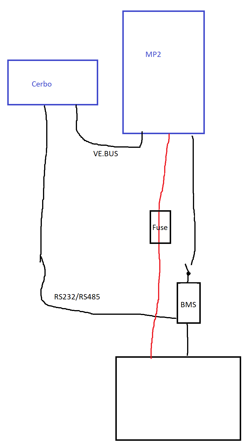
we are currently discussing in another community, how to handle a disconnect of MINUS due to the BMS, if the BMS is connected via RS485 or RS232 to the Cerbo.

The problem is that the BMS uses MINUS to stop the energy flow in case of errors. So if there is an error, MINUS will be disconnected.

The serial connection to the Cerbo is still connected and working and the Cerbo is also still connected to the MP2 via VE.BUS.

Earlier recommenations said, this is not allowed and now you said it works with the newer MP2. So can you please confirm, that the following setup works without problems and MINUS from the serial connection to cerbo to MP2 does not have any ugly sideeffects like acting as backup MINUS if the main MINUS is disconnected?

1658920983920.png

So if the BMS disconnects the battery, the MINUS cable between MP2 and Battery does not allow any flow. So could MINUS from RS232/RS485 cause a high current flow on those thin lines? Or is it decoupled and fine to connect like this?


1 Like 1 ยท
1658920983920.png (18.2 KiB)

Related Resources