question

dognose avatar image
dognose asked

Factor 1 Rule and 100% SoC?

  1. Hello,

    I've just finished my system upgrade, and during regular operation everything works as expected so far. The setup is as follows:

- 3x Multiplus-II 5000
- 1x MPPT 250 (~ 4300 Watts of Solar)
- 1x MPPT 150 (~ 3700 Watts of Solar)
- 1x Fronius Symo 12.5 (~8000 Watts of Solar), AC coupled on AC-OUT.
- 8x Pylontech UC3000S, connected as 4x2 to the busbar, Max. Charge/Discharge Current 296Amps. (That's the rated limit of 8 x 37Amps, while Pylontech denotes a Peak-Rate of upto 8x 200 = 1600A, where the cabling / fusing would support upto 480A total / 120A per Stack (Peak))

1716884690745.png
----

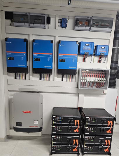
Yesterday, we had the situation, that SoC reached 100% and the sun was shining. Consumption of the house was down to 1000 Watts, so a Feed-In of ~ 14 kW was going on.

(During Summer, that will be the regular operation mode, reached at early Noon)

The setup matches the needs to satisfy the 1:1 rule, but i'm wondering if there is any way to "test" it will work as expected? What will happen, if a grid failure happens during the 14kW Feed-In? Will the batteries - at 100% SoC - still be able to take the hit of ~ 13kW that have no where to go for a split second?

Should I limit the SoC to something like 95% to make sure there is enough "negative Power supply available" at all times? (Can I even limit the SoC with Dc-Feed-In enabled, since DVCC-Charge Current limit is also not operable in that case?)


ac couplingfronius symo
1716884690745.png (383.2 KiB)
2 |3000

Up to 8 attachments (including images) can be used with a maximum of 190.8 MiB each and 286.6 MiB total.

5 Answers
nickdb avatar image
nickdb answered ·

The rule only applies to the PV inverter, it is not relevant to the DC chargers.

Your pack does need to be able to cope with sinking power in the event of an issue.

You mean US3000C?

At 8 batteries you are on the edge of the sizing for 15kVA when grid attached, for off grid (ie grid failure) your’re a bit under. Ultimately the batteries will start moaning if they aren’t happy.

Alternatively, just limit the feed-in a bit.

4 comments
2 |3000

Up to 8 attachments (including images) can be used with a maximum of 190.8 MiB each and 286.6 MiB total.

Alex Pescaru avatar image Alex Pescaru commented ·

Hi @nickdb

According with Victron's recommendations, for 15kVA it will need a minimum of 10 x US2000C modules, which continuously should supply 25A *10 = 250A.

Having US3000C, he has 37.5A * 8 = 300A, so quite (20% more) above the minimum recommendation.

You are saying "for off-grid is a bit under". Which should be the correct sizing?

Am I missing some other piece of documentation for sizing?

Thanks!


0 Likes 0 ·
grua avatar image grua Alex Pescaru commented ·

You wrote:

According with Victron's recommendations, for 15kVA it will need a minimum of 10 x US2000C modules, which continuously should supply 25A *10 = 250A.

Having US3000C, he has 37.5A * 8 = 300A, so quite (20% more) above the minimum recommendation.

How did you calculate that? On the basis of which specific Victron recommendations?

I'm planning to change my Fronius 10 kVA from ACin to ACout of my 3x MP-II 48/5000 and so I am also currently looking into these issues...

0 Likes 0 ·
Duivert NL avatar image Duivert NL grua commented ·
1 Like 1 ·
nickdb avatar image nickdb ♦♦ Alex Pescaru commented ·

The "standard" power of a 15k inverter is around 300A, excluding peaks, surges etc.

So at 296A this system is just on that requirement.

This is fine for being grid attached, when offgrid (or as a result of failure) all requirements increase as you can't lean on grid.

If running to the limits, and PV inverters are the variable here, hence the 1:1 rule, it never pays to be at the edge.

Reducing feed-in would be a better idea so the system doesn't have to deal with a 14kW surplus.

Batteries aren't cheap, imo, I would rather be careful.

0 Likes 0 ·
grua avatar image
grua answered ·

First: the topic opener @dognose writes that he has a Fronius Symo 12.5 (= 12.5 kVA) with 8000 watts of solar. I interpret this as 8 kWp solar panels on the 12.5 kVA PV inverter. The smaller value of 8 kW then applies for the factor 1 rule.

I then calculate as follows:

The batteries are discharged to a minimum of 48 V, for example. If in such a case the grid fails during maximum PV production, the battery must be able to absorb up to 8000W / 48V = approx. 170 A for a short time. But only for a very short time, as the power of the Fronius is then reduced after a few seconds by increasing the frequency (MG50).

If the batteries are designed in such a way that they can always absorb at least 170 A for a few seconds, everything should be fine in terms of battery capacity.

9 comments
2 |3000

Up to 8 attachments (including images) can be used with a maximum of 190.8 MiB each and 286.6 MiB total.

dognose avatar image dognose commented ·

Thx for your reply.


Yes, from these numbers everything looks suitable and for sure is during regular operation.


Right now, the batteries are at 100%, so the BMS' requested CCL is "0A". Battery Voltage is 53.2V, AND I set a CVL in DVCC of 52.8V as well, because higher values (as requested by the BMS) lead to overvoltage errors at the end of a charging cycle.

(That is also mentioned in the victron docu, hence they override the Pylontech BMS request anyway to 52.4, see: "My system only charges the battery to 52.4V" in https://www.victronenergy.com/live/battery_compatibility:pylontech_phantom - However, with 52.8 the system runs without overvoltage errors as well.)

----

So, with regards to the 1:1 Rule, that all however means:

If there is a sudden grid failure, the battery needs to take ~ 170A

- with a SoC of 100%
- with a CCL of 0A send to the system
- with a override CVL of 52.8V

Will the system "kindly" ignore these values and basically "force" the batteries to conusme that 170A for a brief second, or may there be Issues? I mean from the Multiplus' Point of view, there is nothing else they could do with that temporary surplus.

If the batteries would turn off suddenly in this situation, what will happen?

It is obviously a topic, I don't wan't to put to some trial and error testing :P

0 Likes 0 ·
grua avatar image grua dognose commented ·

I think it would be safe if you charge the battery only as much as the CCL still has at least 170A.

But I don't know for sure, but at least that's my own plan.

0 Likes 0 ·
grua avatar image grua grua commented ·

Or latest stop charching as soon as CVL x CCL exceeds 8000 W (for example at CVL 52,8V stop charching latest when CCL <= 8000 / 52,8 = 150A)

0 Likes 0 ·
dognose avatar image dognose grua commented ·
Sounds reasonable, but I assume that the CCL can be ignored by the system:


The bms always sets it's CCL to it's recommended chargelimit, if that would be 100% obeyed, any peak-rating listet for 60 or 15s wouldn't make any sence, because the system would never make use of it. (Well it wont during regular operation)


Also I think that it is not possible to place such a limit, while DC-Feed-In is enabled. As long as the MPPTs will continiously provide power (in order to feed in), the batteries will charge as long as the BMS stops charging on it's own, which is the point when it will report 0 CCL.


I will do some tests about this and let you know, But I assume the only way to keep the batteries bellow 100% with dc-feed-in enabled is to programmatically enforce a certain (negative) grid setpoint when the desired SoC is reached, so the multis start to drain exactly the power comming in from the MPPTs.

0 Likes 0 ·
grua avatar image grua dognose commented ·
Yes, that's very interesting, please let me know!

Thx!

0 Likes 0 ·
grua avatar image grua dognose commented ·

I will also be testing this over the next few days. MPPT is present and DC Feed In is activated. I will then try to set the CCL = 0A at SOC < 95% in the DVCC while the MPPT is still producing. We'll see if the battery continues to charge anyway...

My battery is a Gobel Power 115kWh with 150A BMS.

0 Likes 0 ·
grua avatar image grua dognose commented ·

But also something completely different should work:

As soon as the desired state of charge (e.g. the desired SOC or the desired battery voltage) has been reached, set the CVL in DVCC to the currently actual voltage. The battery should then stop charging and remain at the current voltage

I will also test this. I think I have already tried this some time ago with my Gobel battery. I'Il have to test it again...

0 Likes 0 ·
dognose avatar image dognose grua commented ·

Tested exactly this today.


I've set CVL to 50.5, while the battery reported 50.6V

At first, it didnt have any impact, batteries kept going as usual.

Strange thing is, that the MPPTs showed a battery voltage of ~49, dunno why their reading is different than the one shown in VRM.

After a while however, I noted that the batteries are stuck at about 90% with only 200,300 watts beeing charged.

By that time i didnt check the voltage shown in the mppts details, but maybe that's the point, where "they" recorded the desired 50.5 V?

But weather is s*** today, so cant tell by now, if it worked, or if the stuck at 90% was due to little overhead available.


However, I think the Pylontech batteries are using passive Balancing, which means not charging them to 100% SoC for longer periods isnt an option anyway.


0 Likes 0 ·
nickdb avatar image nickdb ♦♦ dognose commented ·
Considering the batteries are capped at 52.4V, you are not going to get a full SOC being 1.9V below what they require. They will also not balance at that voltage, so it's not great for battery life.


0 Likes 0 ·
grua avatar image
grua answered ·

What I really don't like about our considerations so far is that we don't charge the battery to 100% so that we still have enough buffer in the battery in the event of lost grid until the Fronius power is reduced by increasing the frequency. Firstly, this wastes battery capacity and secondly, the battery is no longer balanced.

I have therefore thought again about how the battery can still be fully charged despite being too small according to the Factor 1 rule:

As already mentioned, I have a combination of a 14.3 kWh battery (Gobel Power) and a Fronius 10 kW inverter.

We have already discussed this for batteries that are not full: Factor 1 rule would actually prescribe a battery with at least 10 * 3.2 = 32 kWh for Fronius 10 kW. However, if the battery is never discharged below 48 V, a smaller battery is sufficient as long as the BMS reports CCL of at least 10000 W / 48 V = 208 A. Or if you have a 200 A BMS, it is sufficient to permanently limit the Fronius to 48 * 200 = 9.6 kW.

However, this 200 A current surge may only last a few seconds at the time of the grid failure until the Fronius is regulated down to the charging current limit set in the Victron DVCC by increasing the frequency.

However, grid failure at full battery status is still a cause for concern when the BMS reports a lower CCL to the Victron. I have now come up with the following idea for this:

According to the Factor 1 rule, the Fronius may officially only deliver 14.3 / 3.2 = 4.5 kW with a 14.3 kWh battery.

My plan would now be to have the Fronius produce 10 kW at full power as long as grid is available and BMS reports CCL >= 200 A.

However, as soon as the BMS reports a CCL < 200 A when the battery is getting full, I will limit the Fronius output to 4.5 kW. It then officially complies with the factor 1 rule. It should be possible to specify the power limitation of the Fronius via Modbus TCP, which could be implemented in Node-RED.

As soon as the BMS reports CCL >= 200 A again due to an empty battery, I increase the power limitation on the Fronius back to the full 10 kW via Modbus.

So far my current plan...

2 |3000

Up to 8 attachments (including images) can be used with a maximum of 190.8 MiB each and 286.6 MiB total.

jetlag avatar image
jetlag answered ·

In my opinion, there is still enough free "space" in the battery left to take the load of 8kW for let's say 3 seconds, if the battery is not at 3,65V/cell.

We all know, that at the steep part of the charging curve (approx. above 3,45V/cell) the capacity gain is only very small.

But nevertheless, a peak of 8kW (that is 151,5A @ 52,8V) at a sudden grid failure, would only provide a capacity increase of about 0,126Ah within 3 seconds.

This is only >0,1% of the whole stack capacity, so should be no problem at all if the Fronius can be reduced by frequency shift within a few seconds.

So if the battery is not always loaded up to a max voltage/cell, I see no problem there.

3 comments
2 |3000

Up to 8 attachments (including images) can be used with a maximum of 190.8 MiB each and 286.6 MiB total.

nickdb avatar image nickdb ♦♦ commented ·
It depends on how the BMS is configured to respond to that surge, and how fast the system can respond. It may choose to rollover and play dead.

IIRC the inverters had a ramp time, something like 600W/s comes to mind (might be a bit off here), so your surge could be longer than you expect.

The rule exists for a reason, risking battery life just isn't a good gamble imo.


0 Likes 0 ·
jetlag avatar image jetlag nickdb ♦♦ commented ·
I'm not telling to ignore some rules here. I just calculated some figures to show how many energy is generated in a short time and if this could be a problem.

But neither the 1:1 rule is violated, nore the max. current for the batteries should be over its limit. And if the max SoC of the batteris is set to a corresponding voltage of about ~3,45V/cell or 3,5V/cell, then there should be enough headroom in the batteries to catch up such an grid drop off when AC coupled at AC_Out. Just to be clear. ;-)

1 Like 1 ·
dognose avatar image dognose jetlag commented ·

I think we can conclude, that it all depends on the batteries.

The multiplus have nowhere to route that energy, but the batteries.

Despite any Size, any battery will reach 100% SoC at a certain time and therefore report 0 CCL to the system.

If it still is able to absorb that few second surge is something most likely only the battery manufacturer could answer.

I will try to get a qualifiied statement from Pylontech about this.

I don't think it won't be an Issue, technically you can always overload batteries to some extend - but in the case of BMS managed batteries, theres a 3rd player in that game who might take counter-measures to avoid the (even short) overload.

0 Likes 0 ·
jetlag avatar image
jetlag answered ·

The point is, that you define the 100% SoC state.

And as long this 100% SoC point is not defined at the absolute max. rating for the cell voltage at 3,65V/cell, then the battery is always physically able to take some energy without harm.

The question is now, what the BMS will make at this high SoC level and if the MP2 can still drop the energy into the battery if the CCL is set to 0A?

2 comments
2 |3000

Up to 8 attachments (including images) can be used with a maximum of 190.8 MiB each and 286.6 MiB total.

grua avatar image grua commented ·

I don't know for sure, but I assume that a BMS only 'reports' the CCL, but does not yet react immediately if the CCL is exceeded. A BMS wil probably only switch off if the limit values configured in the BMS for over/undervoltage are exceeded/fallen below or the cell temperature becomes too high, etc. At least that is my assumption.

1 Like 1 ·
jetlag avatar image jetlag grua commented ·

I agree, this is also my assumption. And for my DIY JK BMS I exactly know the values, but I'm not sure if you can adjust/change this in a Pylontech battery and what is set as default.


1 Like 1 ·

Related Resources

AC-coupling and the Factor 1.0 rule


AC-coupled PV with Fronius PV Inverters


Additional resources still need to be added for this topic

Additional resources still need to be added for this topic