question

kenzo avatar image
kenzo asked

Passthru isn't only passing thru

I would like to get my AC-coupled system into "Passthru" mode on sunny days so the MP-IIs don't waste energy on (dis-)charging the battery packs when there's no need to.

This seems to have somewhat worked:

1716823549482.png

1716823607653.png

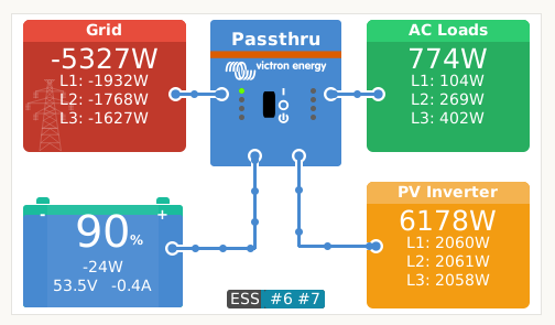
However, as you can see above and below, one battery pack is still allowed to get a small charge of ~0,4A:

1716823482681.png

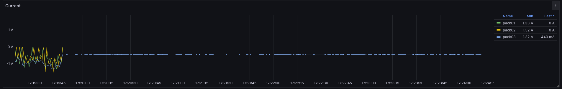
What's a good way of figuring out why the Multiplus-IIs still allow the system to charge? And why doesn't setting the maximum charge current to "0" force actual passthru?

Multiplus-IIDVCC
1716823482681.png (37.7 KiB)
1716823549482.png (37.1 KiB)
1716823607653.png (7.1 KiB)
2 |3000

Up to 8 attachments (including images) can be used with a maximum of 190.8 MiB each and 286.6 MiB total.

4 Answers
Alexandra avatar image
Alexandra answered ·

@kenzo

It is interesting how it is only one pack 'taking a charge' and not the other two.

Why the conclusion it is the Victrons fault? If it was all three taking a small charge, I would be more inclined to agree with the conclusion in your post. Potentially here the one pack needs to catch up to the rest in voltage and balance (or maybe it has a resistance difference), that is a more likely reason - the battery.

2 |3000

Up to 8 attachments (including images) can be used with a maximum of 190.8 MiB each and 286.6 MiB total.

kenzo avatar image
kenzo answered ·

It's not about anybody's fault - it's trying to understand why a setting like DVCC max charge current isn't honored. If there's a current available to the battery pack, it may or may not take it. But if I use a physical switch to turn off all current, the battery wouldn't be able to consume anything either. So the question is: Why is the MP-II delivering any current to the battery when the setting is "0"? Why doesn't it behave like a software switch (until/unless any situation appears where this may be considered harmful/damaging etc.)?
Why do I see "Passthru" as the mode (which is what I see when communication is severed as well, when there's actually 0A going through the wire) but it's actually charging at the same time?

There might be a good reason for this, all I'm trying to do is find the log/reason so I can understand it better. So much of the internal implementation details are a black box. Where's the debug log? ;)

2 |3000

Up to 8 attachments (including images) can be used with a maximum of 190.8 MiB each and 286.6 MiB total.

nickdb avatar image
nickdb answered ·

The system is battery lead, you’re trying to force a behaviour by setting the inverter limit to 0 and the charge current to 0. Hence the status codes 6 and 7.

It is not intended for that purpose.

Batteries will always be lent on, physics prohibits a zero value not to mention measurement inaccuracies at low levels.

If you want 0 usage, fit a bypass switch.


2 |3000

Up to 8 attachments (including images) can be used with a maximum of 190.8 MiB each and 286.6 MiB total.

kenzo avatar image
kenzo answered ·

> It is not intended for that purpose.
What is the purpose of being able to set a 0 value for (dis-)charge if it isn't setting (dis-)charge to 0A?

> physics prohibits a zero value
Turning off the charger would lead to a zero value. Why would you think that that's impossible?

> If you want 0 usage, fit a bypass switch.
Like I mentioned, I can do this manually and it works well. As outlined above, I'm trying to understand what the purpose of ESS #6 (User configured a charge limit of zero) and #7 (User configured a discharge limit of zero) would be if not to make it zero.

3 comments
2 |3000

Up to 8 attachments (including images) can be used with a maximum of 190.8 MiB each and 286.6 MiB total.

nickdb avatar image nickdb ♦♦ commented ·
If you do some research you will find that victron don’t want ccl set to 0. It can’t be honoured all the time. Same applies for a BMS. Just the way it works, there is far more to it than you are considering.

There isn’t a separate charger and inverter, its one device that changes between the two modes, likely why there is a charger or inverter only switch.

It will not behave the way you are expecting.


0 Likes 0 ·
kenzo avatar image kenzo nickdb ♦♦ commented ·

I'm sure there are a lot of variables, which is exactly the reason for asking here. However, look at my initial screenshot: there's plenty of power available from the pv inverter, and there is no need to charge the battery since it's obviously not below any critical threshold. So why is it beside the point to expect the setting to be honored under these exact circumstances?
I'm sure there'll be a ton of failsaves to consider. In a stable system however, I would like to understand what made the charger deliver a charge instead. Is that really so far off?

0 Likes 0 ·
nickdb avatar image nickdb ♦♦ kenzo commented ·
For the same reason the system is not supported without a battery (you are effectively trying to logically remove one). Energy is always flowing in/out of the battery. It is the architecture of the system.

Setting a limit, and a 0 limit are not the same thing. It simply cannot honour 0A.

Why is this an issue?

Is your voltage increasing? (usually only seen on undersized packs)

While the system will favour grid, this is a battery-centric architecture and it will always have small amounts of energy moving, sometimes larger amounts, depending on load/generation variances.

As already stated. a low measurement is unlikely to be accurate anyway.


0 Likes 0 ·