question

jean-paul-1 avatar image
jean-paul-1 asked

Overvoltage on AC-Out due of SMA inverters

My system (OFF-Grid):

3x Multiplus 48/5000 in paralel

3x SMA Sunny Boy 3000 on AC-OUT

2x MPPT 150/60

6x 5.12kWh BSL Batteries

I've just replaced the lead acid batteries with the BSL package. Everything works fine now but there is one problem remaining.

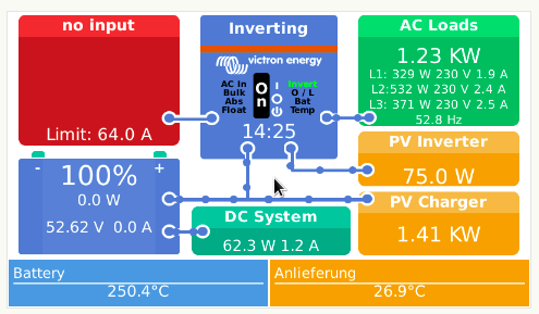
When the batteries are above 95% SOC (bulk charging stops at 95%), I have frequently and AC-Output overvoltage shutdown of the system.

This happens when there is a fast increase in power delivered by the SMA inverters. I never had this problem with the lead batteries (maybe because they are less sensitive?).

The PV Inverter assistant settings are:

Restart PV inverter when battery voltage is above 51 volt

Frequency shifting settings are: 50,2 Hz, 52.5 Hz, 53 Hz

Installed PV inverter power = 9000 W (in master multi)

Installed PV solar panels = 10.700 W (in master multi)

If these settings are used => AC-Output Overvoltage

Now I have changed the installed PV inverter power to 3000 (in master) and PV solare panels to 3500 (in master). This thinking that with the 3 multi together will also be 9000 / 10700. Don(t know yet if this will work.

The whole system just responds to slow on sudden big changes in SMA output increase.

Anyone any idea what is happening, what I'm doing wrong or what the possibly correct settings should be?

Thank you

overvoltagebsl
2 |3000

Up to 8 attachments (including images) can be used with a maximum of 190.8 MiB each and 286.6 MiB total.

10 Answers
motti15 avatar image
motti15 answered ·

I have read about this recently: It's in https://www.victronenergy.com/live/ac_coupling:start?_ga=2.14775550.991014739.1714237422-1538888540.1714237422 (the Victron MP2 Manuels -> AC-coupling and the Factor 1.0 rule)
There was something about the possibility of that behavior if there is no grid and a sudden change in AC-Coupled Inverters power output while the battery is already full. That can lead to a charge of the already full battery for a short time and the raising Voltage of the battery leads to the raising AC-Voltage and than the overvoltage shutdown. Normally the frequency will rise and cut the power output of the SMA. But that takes a short time. In that time the AC-Voltage could already be to high.

2 |3000

Up to 8 attachments (including images) can be used with a maximum of 190.8 MiB each and 286.6 MiB total.

jean-paul-1 avatar image
jean-paul-1 answered ·

@Motti15

Yes, this is exactly the problem and I have read about it in that article.

I'm just stuck with finding a solution because it is a very annoying problem on cloudy/sunny days, it can happen continuously .....

At the moment I see only two solutions:

1. Get rid of the PV-Inverters and install MPPT's with the consequence that I have less AC power available during the day, the 12kW is high but with EV-charger on it runs to it's limits in summertime

2. Limits the "full" battery charge to 90 or 95% maximum so that there is always 'room' for short bursts of power. This will 'delay' the issue but will not solve it.

"Now I have changed the installed PV inverter power to 3000 (in master) and PV solare panels to 3500 (in master). This thinking that with the 3 multi together will also be 9000 / 10700. Don(t know yet if this will work."

The above settings didn't work ... yesterday, the same happened.

1 comment
2 |3000

Up to 8 attachments (including images) can be used with a maximum of 190.8 MiB each and 286.6 MiB total.

motti15 avatar image motti15 commented ·

Well 1. isn't really a solution cost and convince wise. AC coupling is one of the advantages of a victron system in a Off-Grid situation and should work well.

And 2. isn't great either and can lead to other problems like unbalanced battery packs with LFP cells.

What should help is to change the charge voltage settings of the batteries (or rather the MPPTs and MP2) . These 5.12kWh BSL Batteries seem to be made of 16s LPF cells (I found that they are 100Ah and nominal voltage 51.2V. LFP have 3.2V nominal per cell => 16 cells.). Setting the bulk voltage to 55.2V will be 3.45V per cell. That's right at the beginning of the steep section of the charging curve. The absorption time should be at least 1h. Than you can drop the voltage to 54.4V. With that the pack charges to nearly 100% (even if these cells are considered 100% at 3.65V.Thats something special with LFP cells) and the balancer can top balance the cells while these AC spikes shouldn't spike the cell voltage and than the AC voltage.


0 Likes 0 ·
jean-paul-1 avatar image
jean-paul-1 answered ·

I understand your explanation but have a few issues (keep in mind I'm not a battery chemist specialist, so I may write things that are incorrect):

The Victron documentation settings are 55V absorption (54.8V with off-grid use) for 1 hour and 55V float. This doesn't make any sense for off-grid use so now I've programmed 54.8V / 54.8V, the Victron (nor BSL) documentation say nothing when used in conjunction with AC-Coupled inverters.

With these settings the batteries are "less" charged then when I would use 55.2V absorption voltage?

So my thought would be now to leave the absorption voltage at 54.8 (battery warranty) and lower the float voltage to 54.2 ? 54.0 ? Would this not have the similar effect as 55.2 / 54.4 ? but with a less full battery?

Cannot try much today since it's rainy and cloudy.

2 comments
2 |3000

Up to 8 attachments (including images) can be used with a maximum of 190.8 MiB each and 286.6 MiB total.

motti15 avatar image motti15 commented ·

That should work as well. There is a great video to this topic from the YouTube Chanel Off-Grid Garage (https://youtu.be/pijPu7t-akM?si=qmCOgbhLSN6KMKo_)

0 Likes 0 ·
jean-paul-1 avatar image jean-paul-1 motti15 commented ·
Thks

Set to 54.8 and 54.0 with 2hrs absorption. We'll see what happens in the next few days.

1 Like 1 ·
jean-paul-1 avatar image
jean-paul-1 answered ·

Still the same problem ....

Voltage on MPPT reduced to 54,80, float at 54

Voltage on Multis even reduced to 54,5, 1h absorption

These settings have only "delayed" the problem but not solved it, it comes later (some days not at all) but it comes depending on the circumstances.

So, I'm in need of a solution because this is very very annoying all the time.

So, please anyone any ideas to help me with this. If not, I'll have to replace the inverters with chargers.

Thanks to anyone with some ideas.

2 |3000

Up to 8 attachments (including images) can be used with a maximum of 190.8 MiB each and 286.6 MiB total.

jetlag avatar image
jetlag answered ·

I think it could be a battery disconnect causing this problem. Could be a classic load dump effect. Meaning, the battery is fully charged and the BMS is disconnecting charging completely at one point. The MP2 then still tries to load the batteries, however can't push the enery into the batteries any more and for a short period of time the voltage could rise. The regulation within the MP2 is maybe not fast enough and that's why a AC overvoltage is generated.

The MP2 is not made to work without batteries, so this could explain it at least.

What are the settings in the BMS? Often the charge limits are set wrong, because are set too early and a battery will disconnect charing at e.g. 3,45V per cell.

Is there a SmartShunt in your system, or how are the batteries connected to the Victron system?

2 |3000

Up to 8 attachments (including images) can be used with a maximum of 190.8 MiB each and 286.6 MiB total.

Alexandra avatar image
Alexandra answered ·

@Jean-Paul

Adjust the frequency shift on pv assistant.

https://community.victronenergy.com/questions/15678/what-are-the-recommended-frequency-settings-for-sm.html

Adjust absorption voltage to 54.8v for offgrid.

https://www.victronenergy.com/live/battery_compatibility:bsl#configuration_settings

How is the sma connected to the GX? The too slow parr might just be the network lag.

Check the comms to the system.

What firmware is everything on? Have the batteries been daisy chained ot bus bar connected as individuals?

2 |3000

Up to 8 attachments (including images) can be used with a maximum of 190.8 MiB each and 286.6 MiB total.

jean-paul-1 avatar image
jean-paul-1 answered ·

@jetlag

CVL = 55.0, CCL = 480, CDL = 600

Is the 55.0 not too low for 16 cells?

There is a victron 500A shunt with BMV connected.

@Alexandra

SMA freq.shift setting are different now. I will adapt to the settings in the link

Absorption voltage in MPPT's are 54,8, in Multiplus the voltages are 54,5, I will set back to 54,8

SMA's are daisy chain connected with ethernet cable to hub, hub is connected to GX with ethernet cable

All firmware of all devices is at the latest version.

Battery connections (2 racks with each 3 batteries)

The negatives of Multi's and MPPT'S go to shunt then to each battery rack

The positives of the Multi's go to DC fuse then to each battery rack

The positives of the MPPT's go to each battery rack

The batteries in each rack are connected parallel / diagonal


2 comments
2 |3000

Up to 8 attachments (including images) can be used with a maximum of 190.8 MiB each and 286.6 MiB total.

Alexandra avatar image Alexandra ♦ commented ·
For better overshoot sinking i would maybe have them in pairs but one long chain is not great the end batteries will be hurt.

BSL terminals dont allow a big enough gauge for your sized system any other way. On minimum you have 70mm²x3 for the inverters, is there at least the equivalent diameter feeding the bus bar from the bank?

If you look on the tech specs part of the sma manual the frequency operating range is given there and will match the post above.


0 Likes 0 ·
jean-paul-1 avatar image jean-paul-1 Alexandra ♦ commented ·

Programmed settings today.

Abs and float in Multi's set to 54.8, MPPT's set to 55,0. Freq shift set to 51-51,8-52.

Started everything and waited for full load and production.

Switched EV charger off (7.5 kW) with SMA power at 9 kW, direct AC overload and shutdown.

Now i have changed the PV assistant. Changed in the master multi to 9000 inverter power and 10240 PV installed panels.

Before it was 3000 and 3500 because I thought with 3 Multi's each should have 1 third in the assistant.

Will test tomorrow to see what happens.

Battery rewiring needs to be done, I agree. This is now not an optimal setup for the batteries.

0 Likes 0 ·
jetlag avatar image
jetlag answered ·

The charge voltage limit of 55,0V is fine. A lot people use 55,2V, but this should not make a difference and cause the problem. I would like to know where is the protection level for the cells, because maybe one cell will peak out at high SoC and the BMS will turn off laoding.

1 comment
2 |3000

Up to 8 attachments (including images) can be used with a maximum of 190.8 MiB each and 286.6 MiB total.

It is a 1C charge to 54v (according to their documents) then CCL is reduces to 0.2c (so balancing.)

They have slow balancing. So best not to go higher than that. They overshoot and get grumpy.

This is an offgrid application so the voltages specified are different. DC mppts at 55v (float and abs) are fine.

Bias the charge to finish with the DC mppts and leave the AC pv to run loads. And overshoot can be absorbed.

0 Likes 0 ·
Paul B avatar image
Paul B answered ·

This is what I have done on my system when I get this issue.

And it fixes the issue. It's been on now for 5 years and working fine

1. I have inserted a contator between the grid tie inverters and the victron ac out conection system.

2. I then use the cerbo relay one to control the contractor

3. I then use the generator auto start feature to activate the relay

4. Only use voltage control. Start gen if battery is lower than say 53v for 1 sec. Then set Stop gen if battery voltage is over 57V for 2 sec.

This will then isolate the pv grid tie inverters and they will shut down.

Down side, it's not overly good for the pv inverters to shut down on a dead cut, however they do it if the mains fails on a house so it's not much diferant.

This is a work around but it solved this exact issue that I was having.

Of course modify the settings to suit your requirements.

By the way I used the cerbo relay to turn the contractors driving coil on and off using 220v

2 |3000

Up to 8 attachments (including images) can be used with a maximum of 190.8 MiB each and 286.6 MiB total.

jean-paul-1 avatar image
jean-paul-1 answered ·

@Paul B

I've thought about this possibility but I have some second thoughts:

1. It's a very "brutal" method of bypassing the problem

2. In cloudy weather (with strong sun bursts) this would lead to continuously on/off switching of the inverters keeping in mind it takes about 30-40 seconds before the inverters start delivering power after disconnecting which means that basically the inverters become useless.

3. When using the generator flag with a 2 seconds delay, I don't see how this can be faster then the Multiplus response to freq.shif. In my situation the Multiplus switches off in a fraction of a second. If the system would have 2 seconds to spare, I would think that the Multi would have enough time to deal with the overvoltage.

Sorry to say but the Victron should be able to deal with this. They have certified the BSLBatt and SMA inverters to be compatible with their products ..... and like said in the beginning, one of the biggest advantages of Victron is that it should be working with AC coupled inverters. I doubt if they have ever tested this setup ....

Their EV charger is also not compatible with Off-grid systems, strange since Victron is mainly and Off-grid product supplier.

2 |3000

Up to 8 attachments (including images) can be used with a maximum of 190.8 MiB each and 286.6 MiB total.

Related Resources

Additional resources still need to be added for this topic