question

keivn avatar image
keivn asked

isolation transformer 3600 section 2.3 (figure 4 pg7) in the manual states: (poorly worded)

The 3600-isolation transformer manual on page 7 (section 2.3) figure 4 states:

If the boat is on shore power (winter period or maintenance) the manual goes on to explain the jumper wire configuration.

Does this wording actually mean, that if the boat is OUT OF THE WATER on shore power, for winter period, or maintenance you connect the PE to the J34 connector? (and disconnect the PE to J34A connector)?

These two details are very important to understand, after hours and hours of scratching my head over these jumper wire instructions I now believe these jumper wires are connected in this manner.

Most of the time the jumper wire goes from PE to J34A. If the boat is OUT OF THE WATER for storage, or maintenance, then connect the PE to J34 jumper (and disconnect the PE to J34A jumper)

Is my thinking correct?

Thank you for your review,


For as important as this part of these instructions are, they are horribly written, with lack luster detail Victron needs to revisit this wording and fix it.

wiring diagram
2 |3000

Up to 8 attachments (including images) can be used with a maximum of 190.8 MiB each and 286.6 MiB total.

7 Answers
pwfarnell avatar image
pwfarnell answered ·

In my manual copyright 2008 I find no problem because it says

If the boat is on shore (winter period or maintenance) the manual goes on to explain the jumper wire configuration.I

It does not say shore power it say on shore, i.e. on land, the other option in that figure is floating. If your manual is the same revision as mine then check you have not added "power" bevause you expect this after "shore".

Secondly, if you go to the manual dection on the Victron isolation transformer page, you will see the Feb 2003 version is clearer.

https://www.victronenergy.com/isolation-transformers/isolation-transformers-2000va-3600va-7000va#manuals

screenshot-20240423-164201.png


2 |3000

Up to 8 attachments (including images) can be used with a maximum of 190.8 MiB each and 286.6 MiB total.

keivn avatar image
keivn answered ·

Thank you. I'm screen shotting your info you left for me here. You were right about the "on shore' / on shore power theory. it says on shore. not on shore power. thank you for that

My book shows me something different two jumper wires one in black, one in gray

The gray one goes from the top of the PE input to J34 (similar to what you provided) but its not on a push on connector,it goes from what appears to be the top of the imput connections block??

The black jumper appears to tie into that gray jumper and go to J34A Its very strange. to say the least

I'm trying to figure out the directions that came with my unit I bought in 2024. I dont think it wise for me to refer to manuals circa 2008 / 2003 even if they seem more simple it may not be the correct way to hook these jumpers up. I will try to post a screenshot of my directions

1 comment
2 |3000

Up to 8 attachments (including images) can be used with a maximum of 190.8 MiB each and 286.6 MiB total.

pwfarnell avatar image pwfarnell commented ·

The old manual, screen shot attached does show the PE wire from the terminal to J43A or J43 with J43A just being a holding location The new manual suggests that J43A is now connected on the PCB to the incoming PE so you only need to connect this to J43 when on land. You need to confirm what variant your unit is.

17138998921719200091428531614304.jpg

0 Likes 0 ·
keivn avatar image
keivn answered ·

Here is a pic of the inside of my transformer, 3600. I believe the jumper wire is attatched to the top of that green block on the right-hand side via the screw, when the boat is in the water Like normal, the jumper wire attaches to J34A (just as a place to hold the wire and keep it from touching anything and arching or shorting out). Its basically just a loop. When the boat is hauled out of the water for maintenance or storage, then the jumper is attatched to J34 instead of J34A

i think that's it. Judging by the shape of the board J34A is attached (Via the board) to the pe wire.

please let me know if mt thinking seems correct

2 comments
2 |3000

Up to 8 attachments (including images) can be used with a maximum of 190.8 MiB each and 286.6 MiB total.

keivn avatar image keivn commented ·
picture is below sorry I'm new to this
0 Likes 0 ·
pwfarnell avatar image pwfarnell keivn commented ·

Still no picture. Click on the picture icon, then click on the box to get to your files and select a picture.

screenshot-20240424-095346-kindlephoto-274082478.png

0 Likes 0 ·
keivn avatar image
keivn answered ·

Here is a pic of the inside of my transformer, 3600. I believe the jumper wire is attatched to the top of that green block on the right-hand side via the screw, when the boat is in the water Like normal, the jumper wire attaches to J34A (just as a place to hold the wire and keep it from touching anything and arching or shorting out). Its basically just a loop. When the boat is hauled out of the water for maintenance or storage, then the jumper is attatched to J34 instead of J34A

i think that's it. Judging by the shape of the board J34A is attached (Via the board) to the pe wire.

please let me know if mt thinking seems correct

below is the pict of the inside of my unit


1713936872438.png (1.1 MiB)
5 comments
2 |3000

Up to 8 attachments (including images) can be used with a maximum of 190.8 MiB each and 286.6 MiB total.

pwfarnell avatar image pwfarnell commented ·
Yes yours looks like the newer design in the new manual I put the diagram for at first where J43A is connected by the PCB and you need a jumper wire with 2 female spade terminals. Go to the link to get the full new manual.
0 Likes 0 ·
keivn avatar image keivn pwfarnell commented ·

Thanks for the info.

I think you are mis typing J43, instead of J34. I've seen this several times and just want to confirmvictron-2.jpg you mean J34, J34A not J43, J43A.
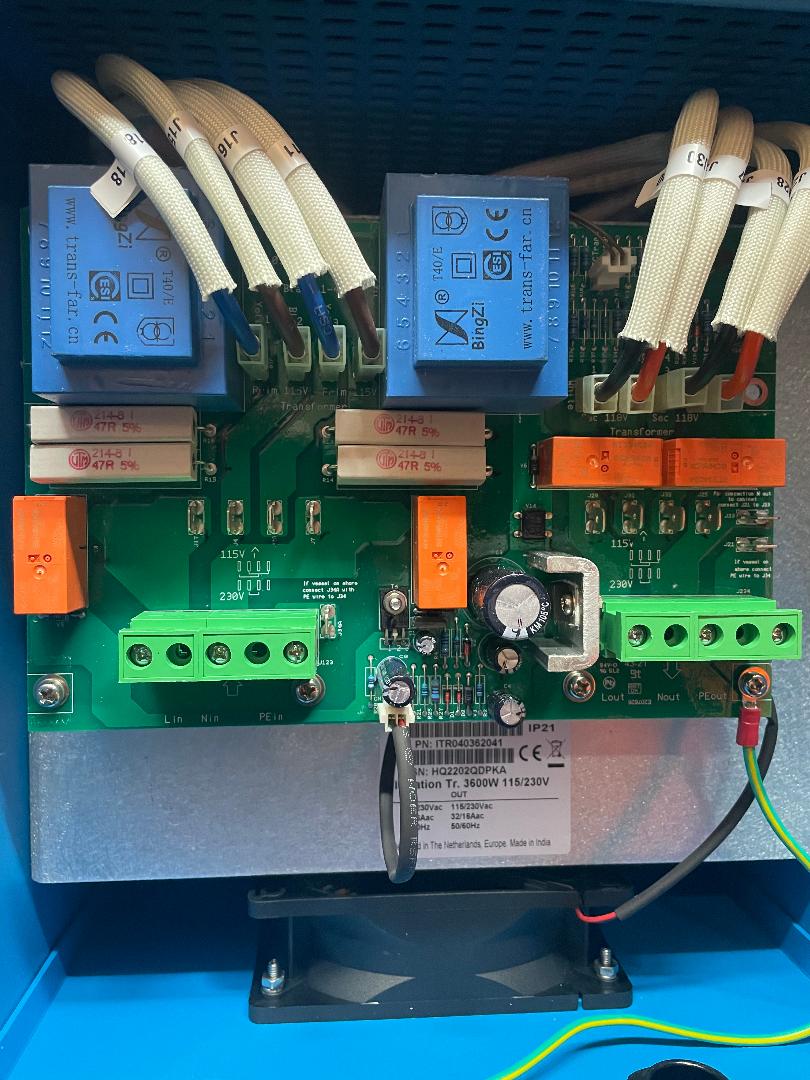

I will look for the link to the new manual. I do not have a jumper wire with two spade connectors with my new unit purchased last week.

The manual I received with my unit should be for my unit. (it should be the "new" manual)

it shows what looks to be a jumper wire coming out of top the green connection block (pcb?) on the left hand side, the jumper is shown coming out of the pe side of the pcb at the top no spade needed, (its permanently affixed) the spade is only on one side of the jumper


a wire with two spade connectors would have to be stored somewhere when not in use, easily lost,

a wire coming from the top of the pcb would simply need to be connected to j34A for normal mode , then moved over and connected to j34 when out of the water i cannot unplug just the J34 connector and let it flop around in the box thats a live wire, but i can connect it back to J34A (as just a place to hold that wire) for normal boat operation, it is just a loop. only one side of the jumper moves back and fourth between J34 and j34A

I will post another picture of what my manual says to do. it's very confusing how victron has made these very important directions so lack luster. they definitely need more (better) detail here.


0 Likes 0 ·
victron-2.jpg (176.0 KiB)
pwfarnell avatar image pwfarnell keivn commented ·
Yes, all the way through I should have been typing J34/J34A.

If you want a confirmation of what to do, get your multimeter out set on resistance and chevk if J34A and the screw next to it (incoming PE) are connected. If so make up an on land wire with 2 6mm female spade connections.


0 Likes 0 ·
keivn avatar image keivn pwfarnell commented ·
i was hoping that I could find some definite answers here, The victron dealer who I bought these two units from (fisheries supply) in Seattle wa. cannot answer my simple questions about installing these jumper wires


there is ZERO support from Victron, The dealer (fisheries) Just tells me to come here and ask questions. they dont know anything about installing the or anything at all about these for that matter

Three days have now gone by and I'm still scratching my head. not to mention the previous week i have spent trying to figure this out on my own...

I never begin an install or power up anything without first knowing / understanding what Im doing, and or how it works, I always follow directions to a tee, And these directions are so LAME there is no way to follow them!

this is absolutely ridiculous, pathetic

I'm returning both of these units and will never buy another Victron anything again, as long as I live

0 Likes 0 ·
keivn avatar image keivn keivn commented ·
i shouldnt have to be making up anything for my brand new transformers, it should all be there ready to go


a wire with two spade connectors? so I can remove it completely, and store it somewhere so it can det lost? or just leave one side unhooked so it can arc and spark??

This is beyond wrong for victron to NOT offer any type of support and have a blog page like idk. a facebook post where people can play guessing games?

I wonder how many peoples boats have caught fire due to this JOKE

0 Likes 0 ·
keivn avatar image
keivn answered ·

victron.jpg

Here is a pic of the inside of my transformer, 3600. I believe the jumper wire is attatched to the top of that green block on the right-hand side via the screw, when the boat is in the water Like normal, the jumper wire attaches to J34A (just as a place to hold the wire and keep it from touching anything and arching or shorting out). Its basically just a loop. When the boat is hauled out of the water for maintenance or storage, then the jumper is attatched to J34 instead of J34A

i think that's it. Judging by the shape of the board J34A is attached (Via the board) to the pe wire.

please let me know if mt thinking seems correctvictron.jpg


victron.jpg (143.5 KiB)
2 |3000

Up to 8 attachments (including images) can be used with a maximum of 190.8 MiB each and 286.6 MiB total.

christern avatar image
christern answered ·

Well, to me it seems as the green/yellow cable is the ordinary "grounding" cable that should always be connected to an "earth-plate" of the boat. The jumper cable is not visible in your pictures but if you look at the small texts on the board you can see just to the right of the left green "hub" where to attach the jumper on one side. The other side of the jumper cable should be connected to the connector just above the green "hub" on the right side. By doing this you connect the shore-power cables ground to the isotrafo while on shore (and the "earth-plate" has no connection to the surrounding water).

2 comments
2 |3000

Up to 8 attachments (including images) can be used with a maximum of 190.8 MiB each and 286.6 MiB total.

keivn avatar image keivn commented ·

hi Christern we are talking about the J34 to J34A connections. which are connected only when the boat is out of the water according to my paper manual (received with my transformer) the pe wire has to be connected to J34A I will add a picture of my manual there appears to be a wire linking the pe wire to J34A coming from the top of the connection block (input side)victron-2.jpg

0 Likes 0 ·
victron-2.jpg (176.0 KiB)
keivn avatar image keivn commented ·

victron.jpgvictron-2.jpgscreenshot-3.png

here are some more pics of what Im trying to figure out on my motherboard it says to connect j34a with pe wire it also says to do that in these pictures on the online manual, however it does not show a connection from pe to the jumper, only the jumper wire plugged in the picture I took of my manual plainly shows some kind of wire linking my pe to J34A WHAT GIVES

0 Likes 0 ·
screenshot-3.png (153.3 KiB)
victron.jpg (143.5 KiB)
victron-2.jpg (176.0 KiB)
keivn avatar image
keivn answered ·

trying to add pictures showing differences in directions connect j34a with pe wire.pdf


2 |3000

Up to 8 attachments (including images) can be used with a maximum of 190.8 MiB each and 286.6 MiB total.

Related Resources

Additional resources still need to be added for this topic