question

saltdaddy avatar image
saltdaddy asked

MultiPlus 2x120/12/3000 Marine Install Planning Questions

I'm planning the install of a MultiPlus II 2x120 inverter/charger into my boat. My shore connection is 120/240 50A and also have an onboard 12KW generator that is also 120/240 50A. The only loads on the boat that are 240V are the three air conditioning units. These 240V loads are fed from their own secondary shore/generator/off selector switch. I have been following the Victron install schematic as it is the closest to my application.

https://www.victronenergy.com/upload/documents/MultiPlus-II-3KW-2x120VAC-12VDC-400Ah-Li-Lynx-Smart-BMS-Cerbo-GX-touch-generator-MPPT-Orion-Tr-Smarts.pdf

I have a few questions/clarifications regarding this install...

1) The Victron schematic above shows that AC Out1 is/can provide No Break loads for 240V out which MultiPlus II manual says that is not possible? Can anyone explain the contradiction here? Is the schematic incorrect?

2) My plan was to only use the MultiPlus to power the 120V loads fed from the first shore/generator/off selector switch. I was going to run the output of that first selector switch to a new 3 pole 50A breaker then to the AC Input on the Mulitplus II and then AC Output 1 back to the panel to the 120V side master breaker. Does anyone see a problem with this plan?

3) I was planning to leave the second shore/generator/off selector providing the 204V as is without running any of it through the inverter. Am I missing something here? Does/should this run through that selector switch to AC Out 2 back to the 240V loads? Seems unecessary to me.

4) The single input/dual output cutoff/battery switch from the Lynx Distributor running to the inverter on the positive...does anyone have a part number/source for that switch they are using? I have found single input/output and dual input/output switches but not the combo.

Thanks and looking forward to the replies.


Multiplus-II
2 |3000

Up to 8 attachments (including images) can be used with a maximum of 190.8 MiB each and 286.6 MiB total.

1 Answer
dc-marine avatar image
dc-marine answered ·

Hi,

The following reply assume you’re in a North America setting.


1. AC OUT 1 should be the no-break output. AC OUT 2 should only be active when AC IN is present.


2. Depending on your loads and usage of the first panel, you may want to consider the PowerAssist feature which can add another 25a of current to your 50a AC input. If you think your total usage could exceed 50a, I would wire the output of the Multiplus with 4awg cable and a 80a 3P breaker as to be able to fully use the PowerAssist feature. If not, then 6awg with a 50a 3P breaker will do.


3. You can leave the second panel alone, but you won’t be able to read the total current draw from your loads as the Multi will only record what is fed through. On the other hand, it allows you to power the second panel using the gen while on shore power for the first panel, which would be fine. If you’re able to deal with managing the total load by yourself so you don’t trip your shore power, you could set the input current limit lower to allow room for the second panel loads while on shore power or generator.


4. The switches you’re referring to are Blue Sea System HD-Series switch part number 3000 and E-Series 5510e. They are simple on/off and on/off double pole switches. The diagram shows the 3000 which has one input stud and two common output studs (they show the grey 3000 switch as a e-series though). They do this because of using a single 4/0awg input split into two parallel runs of 2/0awg output to help with voltage drop. ABYC E-11 doesn’t alllow this unless each conductor is protected by a suitable over current protection device such as fuse or breaker. So you would want a single 4/0awg with a 400a fuse through a regular on/off switch such as the Blue Sea System M-Series 6006, or you would need to fuse each of the two 2/0awg output wires with 200a fuses after the 3000 switch. European standards are different than North America in some applications.


5. Don’t forget that the case ground must be no smaller than 50% of the main conductor of no less than 1 gauge smaller. Meaning 3/0awg for a 4/0awg or a 4/0awg for a double 2/0awg feed. This is also an ABYC E-11 standard for installation onboard a boat and it must be connected back to the main battery, main negative bus or engine block (if using common negative for all systems).


6. Your main DC negative bus should be bonded to the main AC ground bus using at least the same size conductor as your biggest AC conductor (probably 6awg in your case).


Have fun !

12 comments
2 |3000

Up to 8 attachments (including images) can be used with a maximum of 190.8 MiB each and 286.6 MiB total.

saltdaddy avatar image saltdaddy commented ·

Thank you for the information dc-marine, it is very helpful. I am in North America so yes the ABYC would be the standards I want to follow. I have some follow up questions to your reply if you don't mind.


1. The manual states just as you did above and I'm not questioning that...it just was the Victron schematic I referenced that shows you should/could also wire up a 240V MCB to feed 240V no-break loads. I feel like Victron should take this off the schematic as it leads to confusion. Did you notice that on the schematic?


2. I don't really need PowerAssist at this time so that is why I planned to go with the 50A MCB. Will 4AWG fit into the MultiPlus II AC OUT1 terminal block? If it does it may be best to wire it this way just in case PowerAssist is needed in the future. Thanks for bringing that up.

3. I'm not totally sure why the boat was wired with two SHORE/OFF/GEN selectors. Shore power is one 125/250 50A shore power input. Somewhere, behind cabinetry I presume, they have paralleled shore power to provide two sets of L1-L2-N to feed each of the SHORE/OFF/GEN selectors. The 12KW generator is wired the same way as shore power and should theoretically be able to provide the same 50A to both L1 and L2 so I don't know why they would need the second selector. As you pointed out, I guess I could leave that second selector alone, but I think it would also be nice to to capture the current from those 240V air conditioning loads with the inverter for a total picture. To do this I guess I would just remove the outputs of that second selector from the circuit and feed the 240V MCB from AC OUT2.

4. Thanks for the information on the switches. I am using the Lynx distributor so I guess I would like to use the fusing there instead of adding two more fuses to step down the wire size. With that in mind I guess there would be two options? 1st option run two 2/0awg positives from the Lynx using 200A fuses on each lead to the dual circuit battery switch and on to the MultiPlus II. 2nd option would be run 4/0awg with 400A fuse from Lynx to single circuit battery switch and continue with 4/0awg to the MultiPlus II. The total run from the Lynx to the MultiPlus II is probably 18" so I don't think there would be appreciable voltage drop on the 4/0awg? Victron recommends the two 2/0 so maybe that is the best way to go? What is your opinion on this?

5. Seems like the case ground is supposed to be the same size as the DC negative...maybe this was a fairly recent change to the ABYC regarding this? I was planning to use 4/0awg from case ground back to the Lynx ground.

6. I believe this is the case but I'm going to hunt that down and make sure it exists!


Thanks again for your help and hopefully you can find a bit of time to answer the follow ups questions.

Cheers!

0 Likes 0 ·
dc-marine avatar image dc-marine saltdaddy commented ·

Hi,


1. Yes I did notice in the schematic that AC OUT 1 and AC OUT 2 are treated the same. However the Multi you have wont't make 240v, only a common 120v paralleled to both L1 and L2 in invert mode. But again most of their schematic are European market based and sometimes I think they slighty change them for North America but some details can be lost in the translation.


2. The datasheet specs up to 4awg for the AC connections. May be a tight fit but should work. My thinking here is when those A/C units cycles, the start-up draw can cause the Multi to go into assist if you already have a lot of other things going on, so might as well allow it and not worry about tripping shore or output breaker.


3. I would say the boat was wired this way to allow use of generator to complement shore power, especially if you could only plus into a 120v 30a shore while traveling. Depending on your situation and preference, it may be beneficial to leave it that way. What I would do is connect AC OUT 2 to the Shore input of your second Shore/Gen switch. That way when on shore power the Multi will monitor the A/C draw, but still allow direct use of the generator for the A/C units if desired. This involve connecting the combined output of the first selector switch to AC IN, the AC OUT 1 to the first breaker panel and the AC OUT 2 to the Shore input of the second selector switch. However you'll loose monitoring capacity of the second panel when using generator, which is okay because the multi can't assist the 240v loads and it may create something very weird.


4. I would stay with a single 4/0 awg. You're not going anywhere far enough to warrant double 2/0 awg. 3000w load roughly pull 250-280A depending on battery voltage.


5. This is out of ABYC A-31 2020:

*****************************************

31.7.5 DC Grounding Connections

31.7.5.1 The DC grounding conductor (see FIGURE 1, FIGURE 2, FIGURE 3, and FIGURE 4) shall:

31.7.5.1.1 be connected from the metallic case or chassis to the engine negative terminal or its bus, and

31.7.5.1.2 shall be of an ampacity equal to that of the DC positive conductor.

EXCEPTION: The DC grounding conductor may be one size smaller than the minimum size conductor required for the DC current-carrying conductors (see ABYC E-11, AC and DC Electrical Systems on Boats, “Allowable Amperage of Conductors For Systems Under 60 Volts”) providing the overcurrent protection device in the DC positive conductor is rated no greater than 135% of the ampacity of the DC grounding conductor and the conductor is no smaller than 16 AWG.

*****************************************

3/0awg boat cable (105°C) is rated at 327A in engine room, 135% of 327A is 441A, 41A over the 400A fuse rating. Not sure if A-31 has been updated yet but I do not expect this part to change. Most installation uses 4/0awg anyway because 3/0awg isn't always easy to find in stock nowadays. You can always email them and see what they have to say.


1 Like 1 ·
saltdaddy avatar image saltdaddy dc-marine commented ·
Thank you again for quick reply and the follow up answers. You have given me some things to think about in my final planning stages especially running that AC OUT2 to the shore power side of the second selector switch. I really appreciate you jumping in...you're an asset to this community!
1 Like 1 ·
dc-marine avatar image dc-marine saltdaddy commented ·
You’re welcome. I do these kind of installs quite often and every boat is different, so there’s always some brainstorming to do when integrating a new Victron system into the existing setup. You appear to have a pretty good understanding of what’s going on and how to do things the right way, so I’m sure you’ll get it done proper. Cheers.
1 Like 1 ·
saltdaddy avatar image saltdaddy dc-marine commented ·
One last thing since you mentioned having done several of these installs. Do you ever incorporate an inverter bypass on these Victron units? I don't believe I have seen a lot of failures of the equipment through all my reading. It seems like a good thing to do, but space is a premium and that is a lot of switching equipment to find room for. I'm hoping that the pass through of AC would be least likely part to fail if there was an equipment problem. What is your take on that?


Cheers!

0 Likes 0 ·
dc-marine avatar image dc-marine saltdaddy commented ·

Hi, yes good point. I always try to have an inverter bypass relay or interlock breaker, because if your multi ever fails, goes into fault, needs to be isolated, etc you would loose all AC power without a bypass. It does add to the wiring and the space required. It also allow to keep the multi powered for charging while not using the AC pass-through.


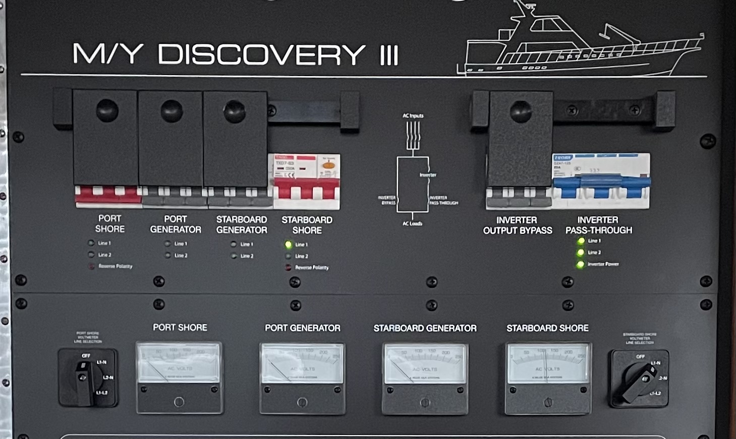
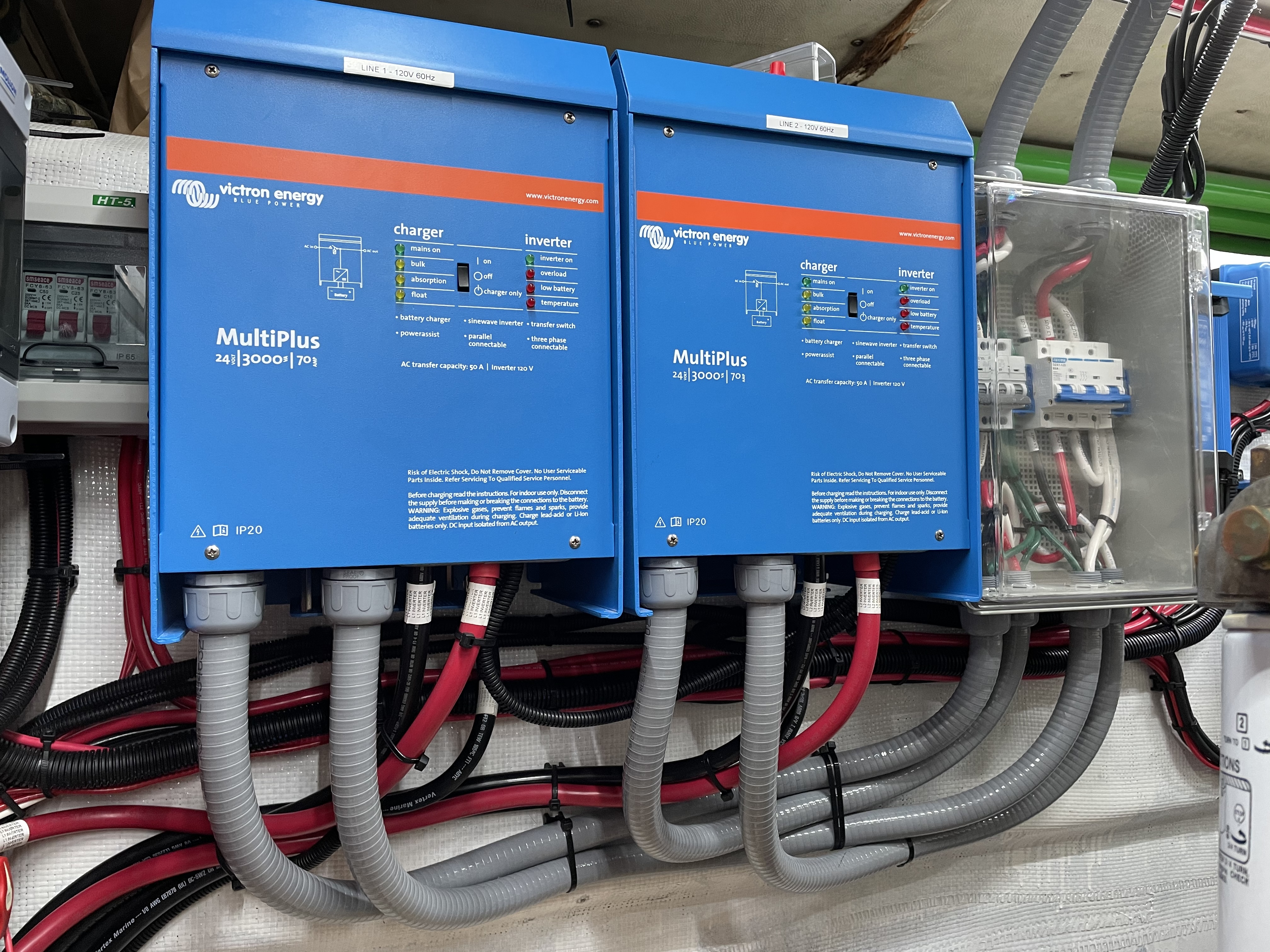
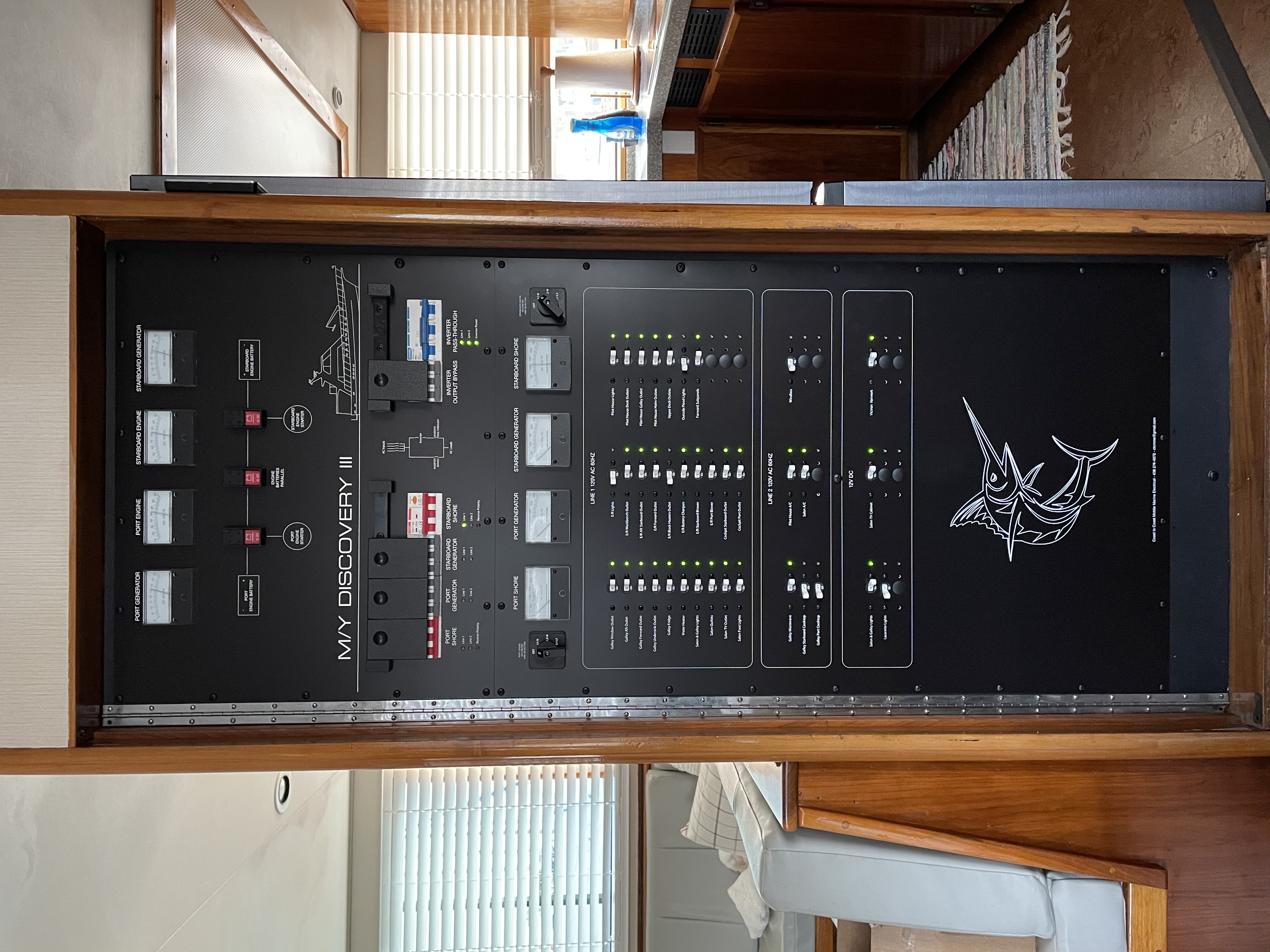
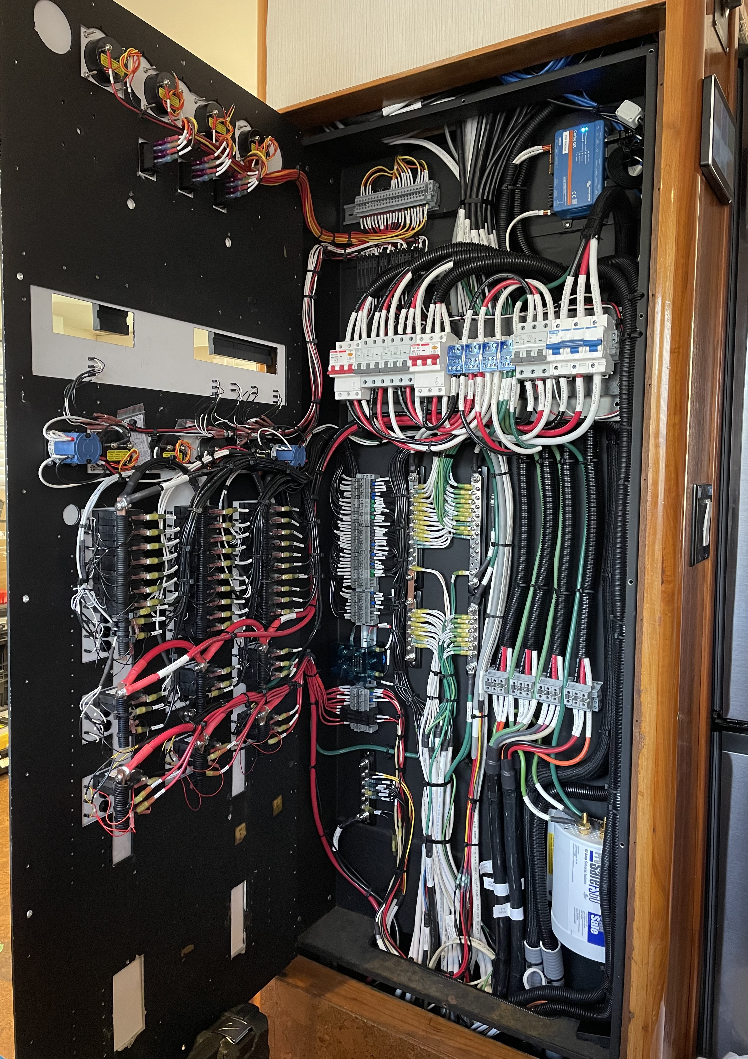
On the pictures you can see how I’ve set the main panel with the interlock for shore/gen input and the inverter out and bypass. I also try to add a input/output breaker box by my inverter so I can fully isolate both AC and DC within arms length of the multi.


d36d2472-60ea-4bd8-a387-19a8e9981121.jpeg

bc87d31a-f296-4460-bd6d-fe1095f82ccd.jpeg

1 Like 1 ·
saltdaddy avatar image saltdaddy dc-marine commented ·
That is a great looking panel. I'm assuming that is aftermarket based on the custom switching. Can you disclose a source? One day I would like to get my panels redone once I figure out what all I'm changing. Did you incorporate ELCI in the above project? I was looking to do that but couldn't find 50A versions, just the 30A from Blue Sea. I would like to modernize all of mine some time down the road and I figure there will be more choices in the future.
0 Likes 0 ·
dc-marine avatar image dc-marine saltdaddy commented ·

Thanks, I design and manufacture my own panels for each installations. This one was 5ft by 2ft. If you take a close look, you’ll notice the red handle MCB, which is a 3P 50a with a 30ma trip circuit, which is what an ELCI breaker is. This one has a built-in CT that trips the breaker if there’s more than 30ma of difference between any of the 3 poles (L1, L2 and Neutral). ELCI breakers are meant to help prevent ESD (Electrical Shock Drowning), which doesn’t really happen in salt water, only in fresh water. If your vessel is never in fresh water then it’s not as critical of an upgrade. But if you’re in brackish water or experience a few feet of fresh water over salt water from creeks or city run-off, then a ELCI can play an important role.

3b3bb099-8a8d-4872-be13-da59a48ac825.jpeg

1 Like 1 ·
saltdaddy avatar image saltdaddy dc-marine commented ·

That must have been a pretty awesome project to work on! I see you have a FB page and I have been looking over your other pictures. You are doing some really nice work! I notice you're in Canada. Is the ABYC what is followed up there? I'm freshwater in Tennessee but plan to travel in the future and that includes salt and brackish. I don't recognized the ELCI breaker you referred to in the picture. Whom is the manufacturer of those? You have a really clean install going there and plenty of room compared to what I'm working with ;-). I'm giving a bypass more thought as well. I may not incorporate one until later though as I will need to find where I will have the space for the extra switching. Still trying to wrap my head around that as well.


Thanks for sharing.


0 Likes 0 ·
dc-marine avatar image dc-marine saltdaddy commented ·

It was a partial refit on an 1982 70ft sport fisher yacht. You can follow my page for more pictures of the projects I do and feel free to comment as well. I try my best to make everything look perfect and to create a proper installation. There wasn't much room to spare on that one. Right now I'm doing 1200ah of lithium with 1300w of solar and twin Multi 3000 on a Navigator 4400. I use mostly ABYC as Transport Canada recognize and adopts the E-11 and other ABYC standards for marine work. Aside of ABYC and basic hull stability certification for Transport Canada, there isn't much else out there fro pleasure craft in Canada. The Coast Guard do have it's safety checklist of items but it usually doesn't pertain to electrical systems, just nav lights, horn, bilge pump, etc.


For the bypass, you can build a box for inverter input/output breakers and incorporate the bypass one (bridge the input to the output).


Here's a link to Amazon for the MCB I use. If you search 50a 3P 30ma you'll find a bunch too. You can also get the brand name ones for a lot more money.

50A 3P 30MA


Blue Sea does make this one with flat rocker. It retails for $840 CAD.

3104 C-Series 3 poles 50A ELCI


0 Likes 0 ·
saltdaddy avatar image saltdaddy dc-marine commented ·
Hey David, you have been very helpful and I think I'm going to go ahead and setup the inverter bypass while I'm doing this as I think the pros outweigh the cons(wiring/space). I have a couple more questions when you get time if you don't mind.


1) In your install above from what I can tell, you used the RCD/ELCI devices on both shore power inputs. Did you not use any on the inverter output? Since the inverter is providing AC power as a source, isn't there the same chance of stray current if something goes wrong? Or are we assuming all boat wiring is OK since the shore protected inputs didn't trip when connected to shore power? I guess that logic works until something unknowingly happens after leaving the dock.

2) I was scouring Amazon to see if I could find the DIN rail terminal blocks(blue covers) that you used for the 6AWG wiring to bus all the SHORE/GEN outputs to the bypass and inverter inputs. Could you please send me a link to those? They would sure cut down on finding room for actual bus bars.


Thanks,

-Jeff


0 Likes 0 ·
dc-marine avatar image dc-marine saltdaddy commented ·

Hi Jeff,


1. You have to look at it this way. If the power source is not onboard the vessel, or is leaving the vessel, then there's a possibility that power could flow back through the water body to the source (like shore power or a genset on a barge or boat you're rafted to.) If the power source is onboard and does not leave the vessel (such as your inverter or generator), then the power doesn't have to use the water body to flow back and if it was to do so (extension cord overboard leaking power back through the propshaft for example), you still are supposed to use GFCI receptacles or breakers for any outlet or appliance that is located outside the boat or in a machinery space (engine room, lazarette, flybridge, cockpit, etc). It wouldn't hurt to have an ELCI breaker on the output of the inverter, however it is not required at this time, as the GFCI requirement is supposed to prevent that.


2. Search for DIN rail distribution block. The model number is UKK125 for the ones I've been using. The 125 refers to the "rated" current for the block. They have sizes such as 80, 125, 160, 250 and 400. The 125 will accept up to seven 6awg (16mm) and one 2awg (35mm), perfect for my application. They have matching dovetails on both sides so they can snap together on the rail.

Google search UKK125

0 Likes 0 ·