Hi guys,
i was wondering if you could take a look and if you have tips i would like to hear it!
tnx in advance
Hi guys,
i was wondering if you could take a look and if you have tips i would like to hear it!
tnx in advance
Hi @MCWopperr
Just a heads up folk get a bit touchy about system design questions on here. But hopefully you'll get some responses.
If you take a very high level view of alternator via orion + solar + lifepo4 + multiplus then all is fine but think there might be a few things with the schematic that would need changing or at the very least are nice to haves.
This isn't a complete list ofc .
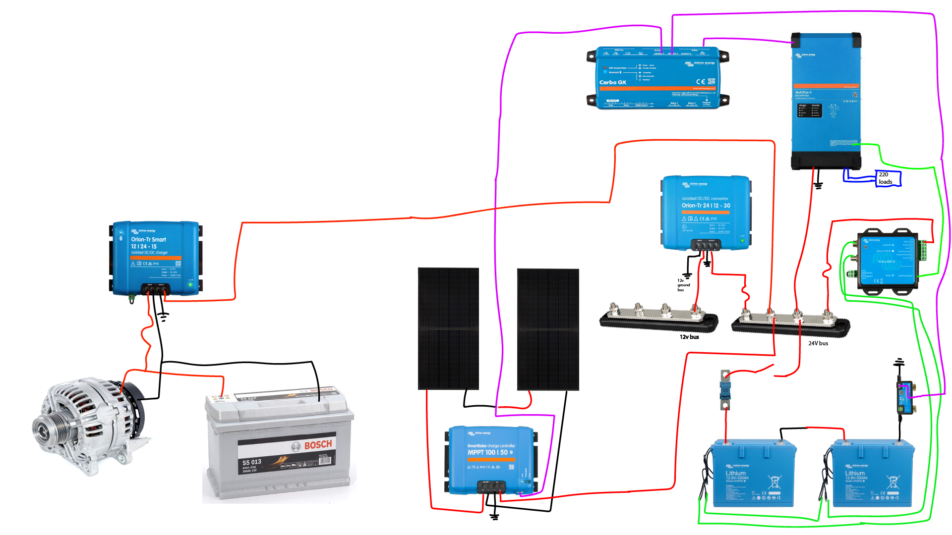
1. I dont work on vans so i might be miles off here but i dont think you can use van chassis the way you've shown in diagram. That's a lot of current being run via chasis... And i imagine the 12v starter battery side of system will be using chasis somewhere. So you'd be mixing 12v and 24v (lifepo4). Which seems like a bad idea (again not a van guy so maybe wrong just seems bad).
Always hate when folk say this to me but given the size (and cost) of all that equipment might be worth getting a spark to help with the diagram at the very least.
2. Add way more fuses/disconnects. I like to have each element of the system fused with it's own disconnect, so you can not only work on specific elements without shutting down entire system but also help diagnose any issues you run into.
I would have fuse between pretty much everything and the main buss bar. As well as one between PV and charge controller.
3. I'd probably add a smart shunt on things you want monitored in gx device. Someone correct me here but i didnt think orion could be monitored directly (unless newer models can). Similarly for the 12v loads if you want/need to monitor the loads add another shunt.
The supplier network is trained for this.
The internet, with its endless opinions of various quality, just isn’t suited to design conversations where detail and context often are lacking.
By all means ask point questions, but broad design threads become problematic.
(It’s tough love, not touchiness ;)
I posted this just to get some people thinking with me over my idea.
I'll sketch my situation a bit better.
I live on a steel ship from 1927, I plan to make it run almost self sufficient so i can anchor for a few days with maybe needing to run my generator after a while.
Currently the boat works on 12v with 2 lead leisure battery's.
I want to go to 24v so it saves me on cable thickness and i believe its a more convinient voltage for this scale of a setup correct me if im wrong
In order to convert to 24 volt i thought that i would only have to add an orion 24v to 12v so it can power my existing 12v busbar. It has just some navigation lights and my water pump on it. The rated 360W should be enough.
Now this i dont know for sure, i planned on making a 24v ground bus bar which all the ground symbols i drawed go to. And this 24v busbar will have a common ground on the propshaft. The 12v part for the engine is all connected to the negative from the starter battery but can it have the same common ground on the propshaft? Like i said this i dont know but i thought that wouldnt be a problem. Because the electrons will go to the battery and any stray electricity can go to shaft.
I wanted to have my 1 alternator also charge the leisure battery's so that is where the second orion comes in. I believe this has the functionality to charge the battery after certain amount of time and stop working when the engine is not running anymore. If that is not the case i will make a on/off switch on the remote port so i can do it myself.
I was thinking about adding a battery protect but for now i didnt include it. I thought that i am home often and know what my draws are. I check my battery state often so i was thinking i didnt need it. But its probably for the best to add it anyway....
I agree that their should be more fuses between connections and switches. Tomorrow ill will put some more time in making the schematic more detailed.
Thanks again for your response! hope to brainstorm some more :)
Also, within the first paragraph of the Victron Community Guidelines section there is a link to their Support page where you can put questions to Victron directly.
Support Requests don't go to Victron, they just get sent randomly to distributors/dealers to try to answer. For system design questions, always best to consult an experienced installer directly.
First thing that struck me is there's a direct short across the left lithium battery.
Unless misinderstood your diagram, both sides of it are connected through the green wires and the bridge between the batteries. Please get professional help.
Hi @MCWopperr as @matt1309 said you are on the right track. As you are using SmartLithium batteries your BMS need to be integrated more into the design. I would suggest splitting the charge, load and inverter circuits. On the charging circuit I would add a Smart Battery Protect (in lithium mode) and connect it to the Allowed to Charge (ATC) signal on the BMS. I would do the same on the Load side and connect it to the Allowed to Discharge (ATD) signal on the BMS. The battery protect can also be used to isolate the loads and charging circuits these also operate in one direction only so be careful with polarity. The inverter will be managed over the VE.Bus as per your design.
You could also wire the ATC signal directly to the charging Orion and mppt and the ATD to the 12/24 v Orion.
I hope this helps.