question

glenn-matthiesen avatar image
glenn-matthiesen asked

Clarification of Application

This is an excerpt from the Victron MPPT 100/50 manual,

3.2 Grounding

● Battery grounding: the charger can be installed in a positive or negative grounded system. Note: apply a single ground connection (preferably close to the battery) to prevent malfunctioning of the system. Is this referring to a central grounding point bus bar?

● Chassis grounding: A separate earth path for the chassis ground is permitted because it is isolated from the positive and negative terminal. Does this mean that the B+ & B- terminals are isolated from the PV+ & PV- terminals on the MPPT allowing the B- terminal to be connected to the central grounding busbar?
Does this statement make the installation of the DC-GFP MNDC-GFP63 GFPD as in the schematic below possible? OR is this statement in reference to the MPPT's case ground?

● The USA National Electrical Code (NEC) requires the use of an external ground fault protection device (GFPD). These MPPT chargers do not have internal ground fault protection. Is this in reference to a GFPD located between the PV array and the MPPT?

The system electrical negative should be bonded through a GFPD to earth ground at one (and only one) location. What is meant by "system electrical negative", the battery terminal neg., the central ground to chassis, the PV-, or on the AC output side?

● The charger must not be connected with grounded PV arrays (one ground connection only) Does this mean the PV- lead must not be grounded? That makes total sense to me BUT, how does this statement impact the installation of the DC-GFP MNDC-GFP63 GFPD as in the schematic below?

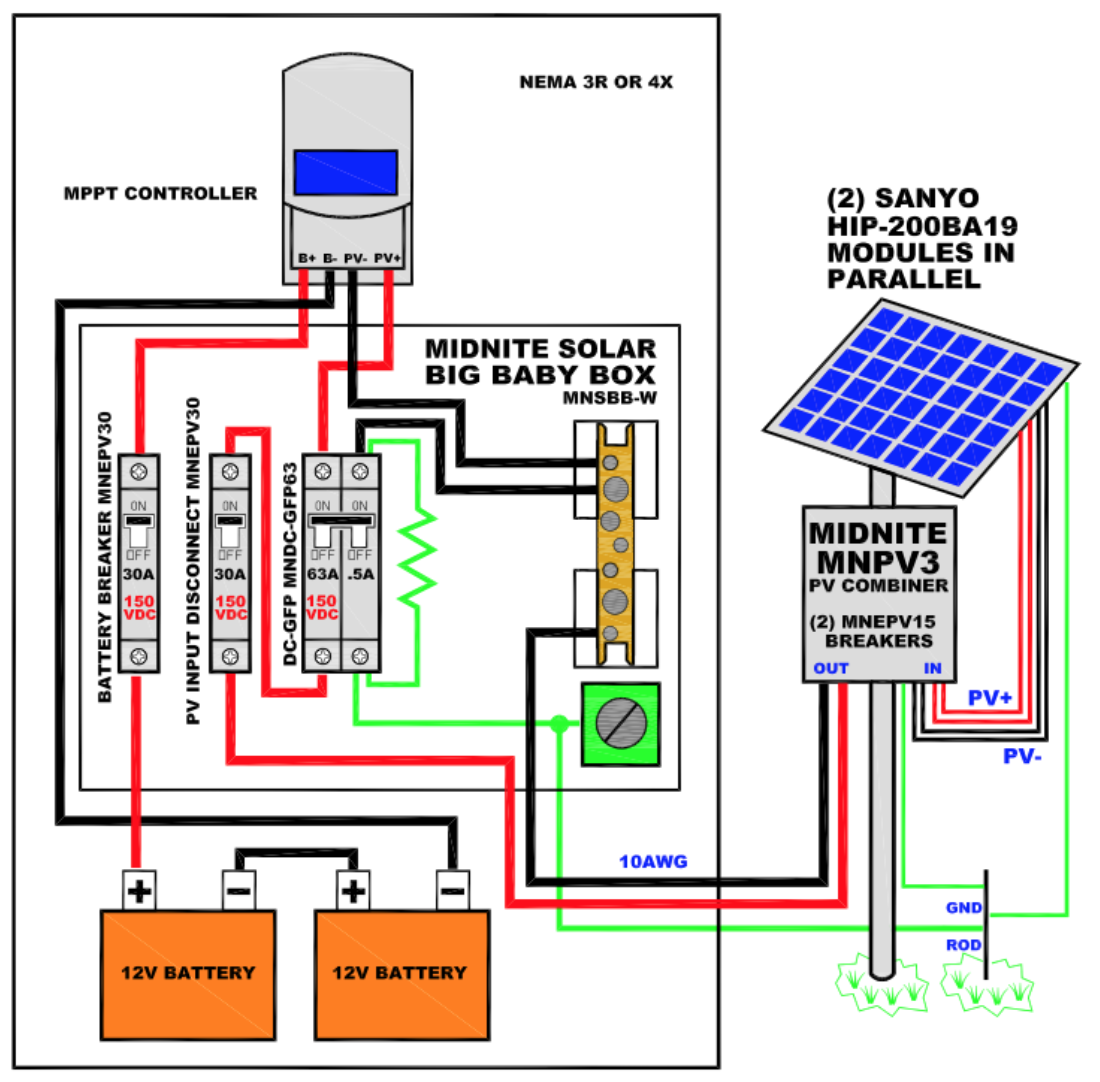
In this schematic, is the DC-GFP MNDC-GFP63 GFPD in effect, grounding the PV- lead or is it just grounding the GFPD itself?
In my application, the battery bank neg. and the B- of the MPPT are connected to the central grounding point. If I install this GFPD, it would also be connected to the central grounding point.

That may work, but if not, Can I isolate the battery bank neg. from the central grounding point?

It does seem a little complicated...

Grounding
2 |3000

Up to 8 attachments (including images) can be used with a maximum of 190.8 MiB each and 286.6 MiB total.

1 Answer
Mark avatar image
Mark answered ·

Hi Glenn,

You have plenty of questions...

Again these are only my thoughts, I recommend that you seek formal advice and confirmation from a qualified electrician /installer.

1- Yes

2- No, I believe that B- & PV- are internally linked (perform a continuity check yourself with a multimeter), but all terminals are isolated from the MPPT body/grounding point

3- Yes, battery negative to ground (but this would only apply if using a 'simple' GFPD that breaks the negative to ground bond in case of a fault)

4- Yes, it doesn't as there would only be a single negative to ground bond (through the actual GFPD)

5- It's grounding the PV- and B- as they should be internally linked BUT ONLY when there is no ground fault / the breaker has not been tripped, if tripped the battery negative will be floating again.

For the GFPD in this setup to work you cannot have any other negative to ground bond anywhere in the system.

2 comments
2 |3000

Up to 8 attachments (including images) can be used with a maximum of 190.8 MiB each and 286.6 MiB total.

glenn-matthiesen avatar image glenn-matthiesen commented ·

Thanks again Mark for your insight.

So if I understand this correctly, I need to disconnect the battery negative and the MPPT B- lead from the central grounding point and connect them to the Multiplus battery neg. terminal, then wire in the PV array and GFPD as per the above schematic.

If I do wire the system in this way, am I creating a grounded PV array contrary to the Victron MPPT 100/50 manual statement "The charger must not be connected with grounded PV arrays (one ground connection only)"?

Will disconnecting the battery neg. from the central grounding point have an adverse effect on the system?

0 Likes 0 ·
Mark avatar image Mark ♦♦ glenn-matthiesen commented ·

With this setup all negative connections on the battery side are wired together (via a busbar or otherwise) with NO ground bond (the GFPD will not work otherwise).

Then one side of the GFPD 0.5A breaker is wired to the PV negative near the MPPT, and the other side to the cenral ground busbar.

When no fault is present the 0.5A breaker will provide a SINGLE bond between negative and ground for the whole system (since the MPPT PV- & B- are internally linked.

The only COMPLETE wiring path between the PV- (at the solar panels / array) and the MPPT PV- is via the PV negative cable. There is NO link/bond between PV- & ground at the actual solar panels / array.

So during all normal operating conditions / times (apart from if a ground fault is present) all current must/will flow through the PV- cables (not through a ground path). In case of a ground fault (PV+ leakage / short to ground) then the PV negative to ground bond will be broken as well as the PV positive path.

Yes if / when the DC system has no negative to ground bond it is not ideal as it is considered 'floating', with no other reference.

This is why the Morningstar GFPD solution is a bit better, since the system always has an uninterrupted negative to ground bond.

0 Likes 0 ·

Related Resources

Additional resources still need to be added for this topic