Any reason I shouldn't do like that?
Can somebody explain why the manual says: "Never ground both the minus of solar array and the minus of battery."?
Ground would be identical to my minus lead to the controller.
Any reason I shouldn't do like that?
Can somebody explain why the manual says: "Never ground both the minus of solar array and the minus of battery."?
Ground would be identical to my minus lead to the controller.
It would be to prevent a ground loop from being created.
Thanks. Studied the concept of ground loop a bit...
I wonder how this can be relevant for charge controllers and if there really is a loop in my case:
All three minus from the controller would go straight to chassis ground - next to the battery clamp.
There is no grounding for the controller's case, right?
I guess a loop would be created in case I ground say the panel and the battery AND pull a negative wire.
So if you don't run a negative wire from the PV then you'll probably be fine since you only have the positive wire going to the MPPT. If the controller's input were isolated from the output then it would be a bad idea.
Do you have short links from the MPPT to the grounding point?
The false measurements that DanC speaks of are valid in the case the there is a shunt in the negative of the circuit somewhere. The shunt may be bypassed via the chassis, but I don't think this applies to your setup.
Having said that, I'd still prefer to have the circuits separated with their own runs to the charge controller. Is there a reason why you can't or wish not to do it that way?
I guess the only shunts involved at this stage would be in the MPPT itself. If I later choose to add measurement equipment it would be connected right at the battery poles. Should be fine I presume.
My plan is to put at least three BlueSolars into the van. Each one will have its own (maybe) tiltable array of panels.
The batteries are sitting in different places in the van. They already share a common ground.
I want to use the controllers to switch different loads - also distributed throughout the vehicle. That is a lot of cable. If possible to avoid half of that it would be great.
I already have some holes in the roof ... I'd rather avoid drilling more.
My idea is to connect all three negative terminals of the controller just outside of it (probably superfluous?) and go shortest way possible to chassis.
If I miss something please let me know. I'm by no means an expert. :D
The positive and negative wiring of the panels needs to be connected directly to the solar charge controller, and nothing else, in order for the controller to accurately monitor the panel output. Otherwise the controller cannot accurately adjust the charging current running from the controller to the batteries. This means the controller should also be wired directly to the batteries by suitably sized positive and negative cables, so the controller also can accurately monitor the actual battery state as part of the charging process. It’s unavoidable to “ground” the controller’s “ground” (not negative) terminal to the vehicle chassis “ground”, the same “ground” as the batteries are connected to. But that’s not the same as running your panel output directly through the vehicle’s “ground”. That’s my view of it, based just on how my system works.
I think my 75V blue solars don't have a separate ground at all.
As long as the connection is good I don't see why measurements would be false. Each negative terminal (PV, battery, load) connected via a solid cable to the same point on the chassis.
Can you explain what exactly would be wrong?
The MPPT will go into error, I don't know if you can damage it but it won't work.
You should ground the panel frames to the vehicle, not the output wires.
Thanks. Good to know.
Problem is in a vehicle normally the negative of the battery is ground.
I am also very curious to know exactly why it is forbidden to connect the PV negative directly to the battery negative (common, grounded, negative busbar). In the USA this would be very normal for many charge controllers (Outback Flexmax, Midnite Classic). The advantage is that you can use a single-pole circuit breaker or fuse on PV positive. If PV negative is not grounded via this busbar then a two-pole breaker seems to be required.
But sometimes there is a functional reason why the PV negative must go via the controller. In the above discussion it has been mentioned that there could be a current measurement shunt in the controller on the PV negative. But this is speculation.
I would like to ask if any Victron staff can tell me whether the battery negative and PV negative are connected directly to each other in the SmartSolar and BlueSolar controllers, or whether there is something in there like a shunt, or what exactly is the deal? If they are connected directly together and the battery negative is grounded, then can we say that we effectively have a negative ground PV array? (Of course the actual ground connection of the negative busbar must only be in one place in the system, and not at the PV as well as at the battery.)
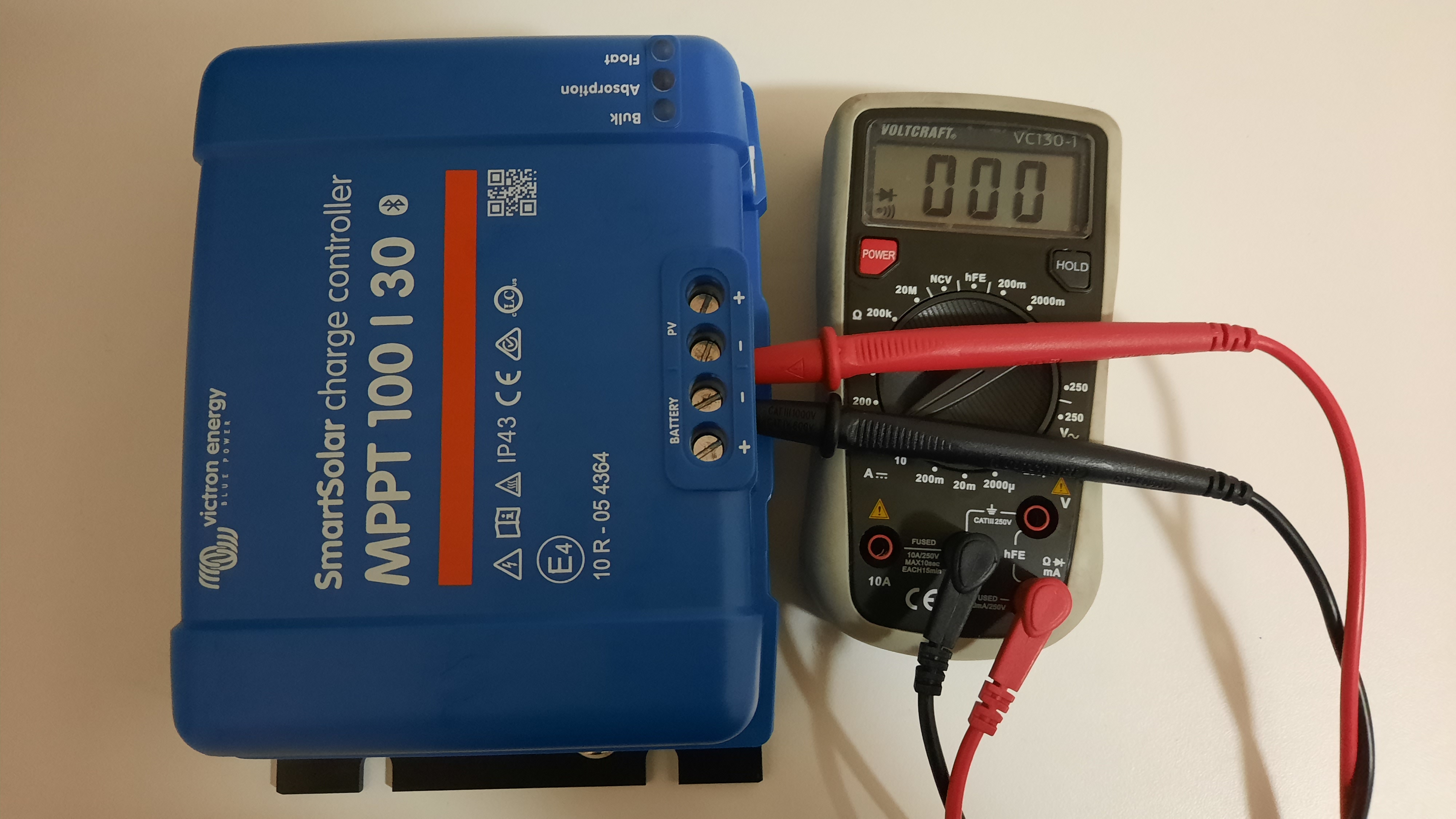
Negative terminals are internally connected? No difference between negative solar or negative battery. Resistance is 0 Ohm measured by resistance measurement.
Can't visually verify the internal connection as there seems no way to open the charger.
I am using a SmartSolar 75/15 and the 100/20 in two setups with LiFePO4 batteries.
I have the controller with the battery so only Solar and Load cables wired from battery box. The BMS requires a direct battery feed in order to jump start the BMS if it stops.
Do I need to run another pair of cables from the battery direct to do this or can I get away with using Load or maybe PV negative if I needed to initiate the BMS?
I just dont want to damage my Controller in anyway as its difficult to get to battery compartment.
Many Thanks
Chris
I remember that the controllers are actually regulating through the negative poles.
So if you bridge them by connecting to the ground you actually short circuit the controller, hence no more controlling possible.
The positive terminals have the same potential...
Not sure if this is still up to date - older regulators were working this way.