question

christopherc avatar image
christopherc asked

BMV-712 Smart monitor is reporting half of current amps (in & out)

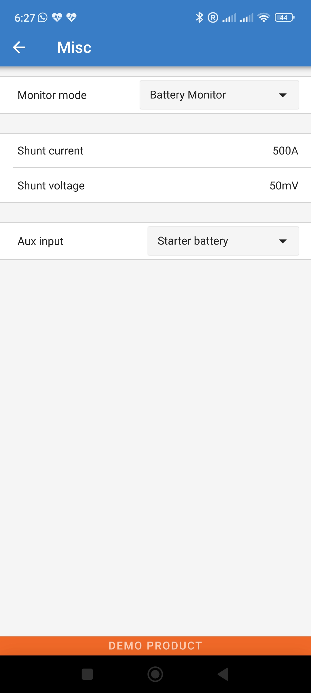
My BMV 712 monitor always reports almost exactly half the amps (either charging or discharging) as reported by my LifeBlue batteries built-in BMS (or my Xantrex inverter when it's operating). Both of these other readings seem correct. It's the Victron which seems wrong.

It doesn't matter whether the charge is coming from the solar or the alternator or whether the load is direct DC or through the AC inverter. As a result, my estimated SOC via the BMV-712 is always well off. My van builder affirms that there are no loads directly connected to the batteries (plus that wouldn't explain why charge current also reads as half). What could be the cause of this?

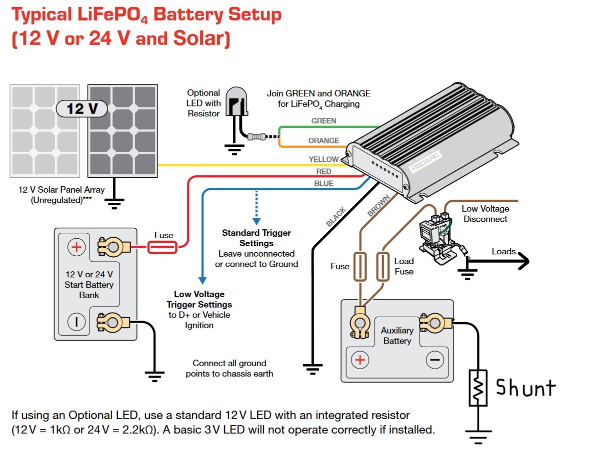
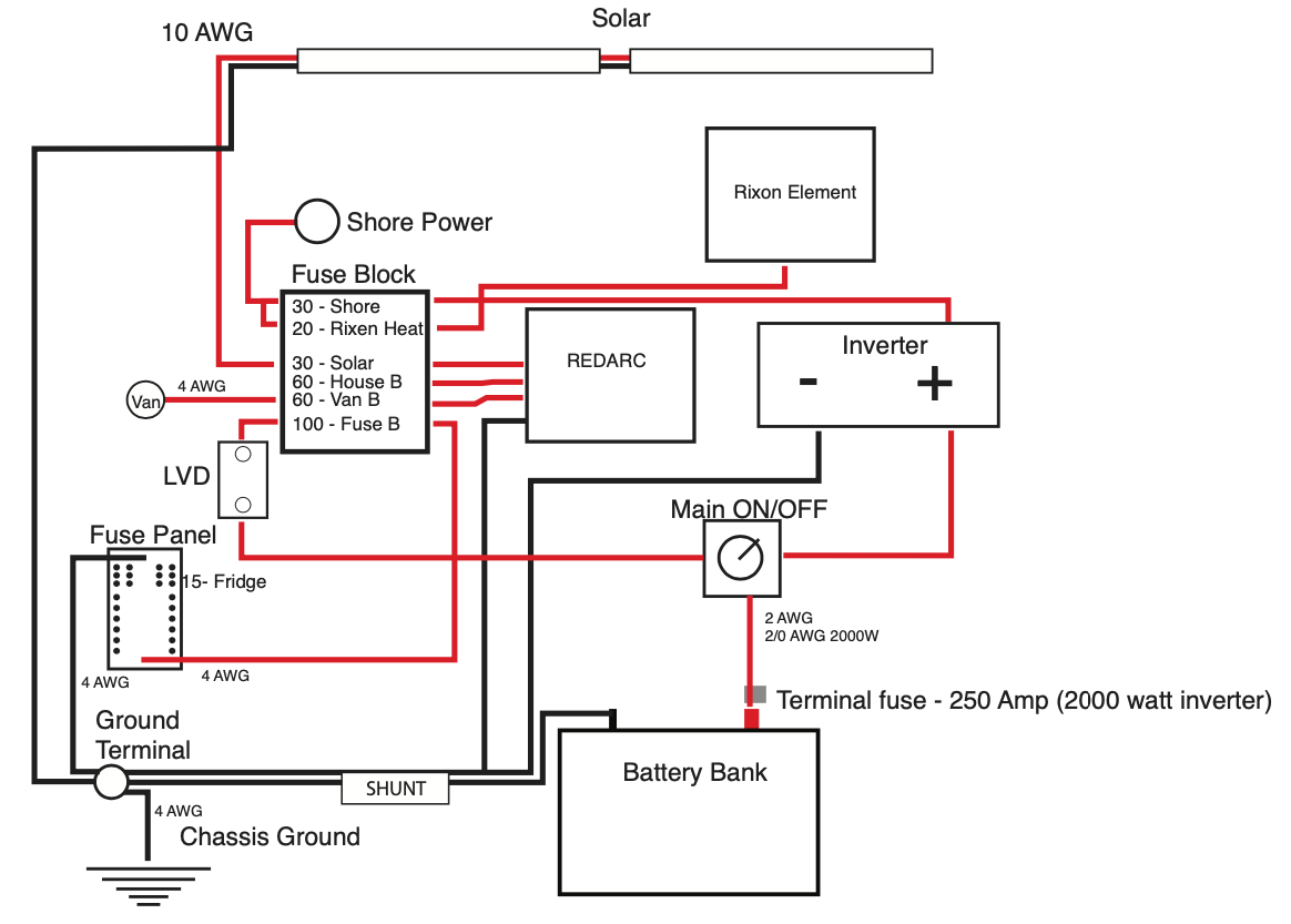
My system includes the Victron BMV-712 monitor, Victron Smart Battery Protect, two LifeBlue 200Ah LiFePo4 batteries, Red Arc 50 amp DC-DC charger and Xantrex 2000 watt inverter/charger.

I've seen a couple of other threads here reporting a similar issue (half current reported by BMV 712) but they're unresolved:

https://community.victronenergy.com/questions/127381/bmv-712-amp-reading-50-off.html

https://community.victronenergy.com/questions/58020/my-bmv-712-shows-less-amps-in-than-does-my-mppt-ch.html

https://community.victronenergy.com/questions/206917/bmv-shows-half-the-current-that-balmor-shunt-shows.html


BMV Battery Monitor
2 |3000

Up to 8 attachments (including images) can be used with a maximum of 190.8 MiB each and 286.6 MiB total.

8 Answers
christopherc avatar image
christopherc answered ·

Alright, I finally found the source of the problem. After more investigation (pulling enough out so I could see and trace connections), I found that there was indeed a second path from the batteries. One to the shunt and one to the negative busbar. (facepalm!) My van builder was certain that his guys would not have done that but there it is. And of course, some of the current was running through the shunt (measured by the Victron) but about half was bypassing the shunt via the negative busbar.

Thanks to all who tried to help!

1 comment
2 |3000

Up to 8 attachments (including images) can be used with a maximum of 190.8 MiB each and 286.6 MiB total.

pwfarnell avatar image pwfarnell commented ·
Thank you for letting us know. It was as expected, a rogue cable and as said previously, it would give a uniform split of current regardless of the actual current.
0 Likes 0 ·
Alexandra avatar image
Alexandra answered ·

@ChristopherC

Look in the manual at zero current calibration.

Is when there are no loads/charge (everything physically disconnected) is the reading zero?

1 comment
2 |3000

Up to 8 attachments (including images) can be used with a maximum of 190.8 MiB each and 286.6 MiB total.

christopherc avatar image christopherc commented ·
Thanks, but it's not a problem with zero calibration. It can still read zero. When there is charge or load though, it shows almost exactly half the actual amps.
0 Likes 0 ·
kevgermany avatar image
kevgermany answered ·

There's a setting in the 712 for the shunt rating. Is it set to the wrong value? Normal is 500A/50mV.

5 comments
2 |3000

Up to 8 attachments (including images) can be used with a maximum of 190.8 MiB each and 286.6 MiB total.

kevgermany avatar image kevgermany ♦♦ commented ·

1000013868.jpg

@ChristopherC


Like this.

0 Likes 0 ·
1000013868.jpg (143.1 KiB)
christopherc avatar image christopherc kevgermany ♦♦ commented ·

Yeah, I had checked that. It is set to 500A/50mV. Thanks anyway.

0 Likes 0 ·
JohnC avatar image JohnC ♦ christopherc commented ·

@ChristopherC

And a 1000A shunt would show the symptoms you describe. This from the BMV datasheet..

1700303391934.png


0 Likes 0 ·
1700303391934.png (73.2 KiB)
christopherc avatar image christopherc JohnC ♦ commented ·

Yeah, this is the one idea that makes the most sense – that would explain why it‘s always reporting almost exactly half of all amps either incoming or outgoing. I haven’t been able to locate or identify the shunt but I think I will ask my van builder about this and report back.

0 Likes 0 ·
christopherc avatar image christopherc christopherc commented ·

shunt.jpg

Well, I located the shunt finally and unfortunately it appears to be a 500A shunt given the engraving visible on the side – and 500A is what my BMV-712 is configured for. I'll still wait to hear back from my van builder though.

0 Likes 0 ·
pwfarnell avatar image
pwfarnell answered ·

Does your battery have a ground connection to the chassis. If so where is this connection, on the battery terminal, the battery side of the shunt or the system side of the shunt. It must be connected to the system side of the shunt. If it is connected to the battery or battery side of the shunt, depending on your other wiring it could provide a parallel unmetered route for battery current. This is a common error on vans / RVs / motorhomes.

2 comments
2 |3000

Up to 8 attachments (including images) can be used with a maximum of 190.8 MiB each and 286.6 MiB total.

christopherc avatar image christopherc commented ·

Thanks but I do not believe there is a chassis ground connection. Also, I don’t think this would explain why it’s reporting almost exactly 50% of all amps in or out, as opposed to some other fraction.

0 Likes 0 ·
christopherc avatar image christopherc commented ·

My van builder/installer has corrected me on this point. There is a single chassis ground on the load side of the shunt.

"All loads have grounds going back to bus bar and that is connected to the shunt. The batteries are not chassis ground anywhere else except that location after the shunt."

0 Likes 0 ·
klim8skeptic avatar image
klim8skeptic answered ·

@ChristopherC As mentioned, it is a common error for the shunt to be bypassed, resulting in bad readings.

Check your wiring.

redarc-new.jpg


redarc-new.jpg (199.1 KiB)
2 comments
2 |3000

Up to 8 attachments (including images) can be used with a maximum of 190.8 MiB each and 286.6 MiB total.

christopherc avatar image christopherc commented ·
Thanks but I do not believe this is the case as my van builder has attested that there are no loads bypassing the shunt. Also, this wouldn’t explain why both all charging and discharging is always reported at almost exactly 50%. It’s not behaving as though some loads or some charge sources are bypassing the shunt.
0 Likes 0 ·
christopherc avatar image christopherc commented ·
Yep, there it was. I eventually pulled enough out so I could see what was going on. There was a second path bypassing the shunt despite my van builder attesting that there shouldn't/wouldn't be.


Thanks for your help!

0 Likes 0 ·
kevgermany avatar image
kevgermany answered ·

You have a few possibilities

Wrong settings, wrong shunt, incorrect wiring and faulty shunt.

You say none of the first three are true. So it must be time to take the shunt/monitor to the dealer.

2 comments
2 |3000

Up to 8 attachments (including images) can be used with a maximum of 190.8 MiB each and 286.6 MiB total.

christopherc avatar image christopherc commented ·

Actually a "wrong shunt" is still a possibility. JohnC suggested above that a 1000A shunt configured as 500A would explain the behavior I'm seeing (50% of amps reported). I have a message off to my van builder to ask about the shunt. I'll update when I hear back.

Update: I finally located the shunt and unfortunately it appears to be a 500A shunt given the engraving just visible on the side (see picture I posted above) – and 500A is what my BMV-712 is configured for. I'll still wait to hear back from my van builder though.

0 Likes 0 ·
christopherc avatar image christopherc commented ·
Indeed... and my van builder is my Victron "dealer".

However, this evening I pulled out enough stuff to see and follow the connections and sure enough, there was a second path from the battery that bypassed the shunt by going directly to the negative busbar. (Arg!) My van builder was quite surprised to hear this since of course he had been saying that there shouldn't/wouldn't be.

0 Likes 0 ·
djsmiley avatar image
djsmiley answered ·

How is it connected? You're mentioning 2 batteries. Maybe the builder has connected the shunt wrong so it only measures current of 1 battery, and the current from the second battery isn't monitored. That also would result into this issue.

Check the negative from each battery. Both should be connected to the shunt, nowhere else.


5 comments
2 |3000

Up to 8 attachments (including images) can be used with a maximum of 190.8 MiB each and 286.6 MiB total.

christopherc avatar image christopherc commented ·

Thanks, but no. The two batteries have built-in BMS with Bluetooth and I can see what each battery is doing and the numbers don’t add up. One or the other may be in standby mode while the other one is accepting charge or delivering power and the Victron BMV will still show half the amps coming in or out.

The two batteries are wired in parallel but if somehow only one was connected to the shunt, I should see the Victron match just that one battery’s measured amp levels but I don’t: I see 50% of the total of both, no matter whether both are operating or just one or the other.

And it’s not the battery BMS that’s wrong because it agrees with the inverter’s power display when that is delivering power.

Thanks for the suggestion though.

0 Likes 0 ·
klim8skeptic avatar image klim8skeptic ♦ christopherc commented ·
@ChristopherC You have an interesting problem.

Given that your installer has claimed the system is correctly installed, but it does not give the results expected, it would now be time to post pictures of your system.

Pics of both batteries, power connection points for the inverter and redarc.

0 Likes 0 ·
christopherc avatar image christopherc klim8skeptic ♦ commented ·

I’m following up with my installer but if it comes to posting pictures here, it will be difficult to illustrate how things are connected via pictures because of how many closely bundled wires and components there are in the electrical cabinet. If it comes to that I’ll try though.

My hope was that because the behavior is so very specifically odd (50% of the total of all loads and charging inputs reported, regardless of which loads or charging inputs are active) that it would point to some specific cause, like the wrong shunt size configuration.

It’s hard to see how a wiring problem could cause this since it’s not like some loads or some charging sources are missing from the BMV readings or like it’s off by a fixed amount. It’s really almost exactly 50% less, regardless whether it’s 2 amps or 20 amps, incoming or outgoing.

Sure seems like a configuration or software issue with the Victron BMV to me, particularly since the two batteries operate and report their status and current separately. They’re not simply sharing the load or charge 50/50.

Anyway, I’m hoping for progress with my installer after showing them this forum thread and the various suggestions from the community, even though we have discussed this issue before.

I guess Victron doesn’t provide direct support – their support page seems to direct only here or to their dealers/installers.

0 Likes 0 ·
pwfarnell avatar image pwfarnell christopherc commented ·
If there is a rogue connection between e.g. the battery negative and the chassis that is in parallel to the shunt then the path through the shunt will have a fixed resistance as will the rogue parallel path so that the current always splits at the same ratio between the two paths giving you what you observe.I am not sure that you can claim that this uniform ratio discounts a rogue connection bypassing the shunt.


There have been many questions on this forum where the van installer is adamant that the install is correct when it isn't and a wrongly placed ground wire is the usual culprit.
-1 Like -1 ·
christopherc avatar image christopherc pwfarnell commented ·
That’s good to know – I wasn’t aware that this could create such a 50/50 effect. Thanks, I’ll pass this along to my installer.
0 Likes 0 ·
christopherc avatar image
christopherc answered ·

Just to update this thread, I heard back from my van builder/installer:

"Maybe it is the shunt that is bad? Seems odd, but that could be it. There is a chassis ground but it is on the load side of the shunt, then all loads have grounds going back to buss bar and that is connected to the shunt. The batteries are not chassis ground anywhere else except that location after the shunt."

1700534473522.png

I'll be continuing to investigate and perhaps replace that shunt. I'll look to see if I can verify the actual wiring matches this design layout. I'll update this thread if/when we figure this out.


1700534473522.png (103.8 KiB)
1 comment
2 |3000

Up to 8 attachments (including images) can be used with a maximum of 190.8 MiB each and 286.6 MiB total.

kevgermany avatar image kevgermany ♦♦ commented ·
I assume you have separate fuse boxes for AC and DC.

Note that your shunt will only measure current through the battery. All loads will initially be supplied by shore or solar and will not register on the shunt, until the battery supplements the other sources. But thos doesn't explain the constant 50% deviation, it would vary as loads change.


0 Likes 0 ·