question

usernamepasswordbs avatar image
usernamepasswordbs asked

Error 24, External CT is checked in Ve.Config.

Hi,

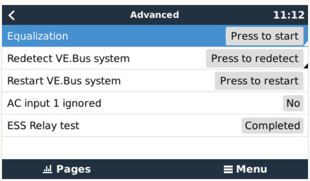
Error 24 after loss of mains even though External CT is checked and firmware is version 496.

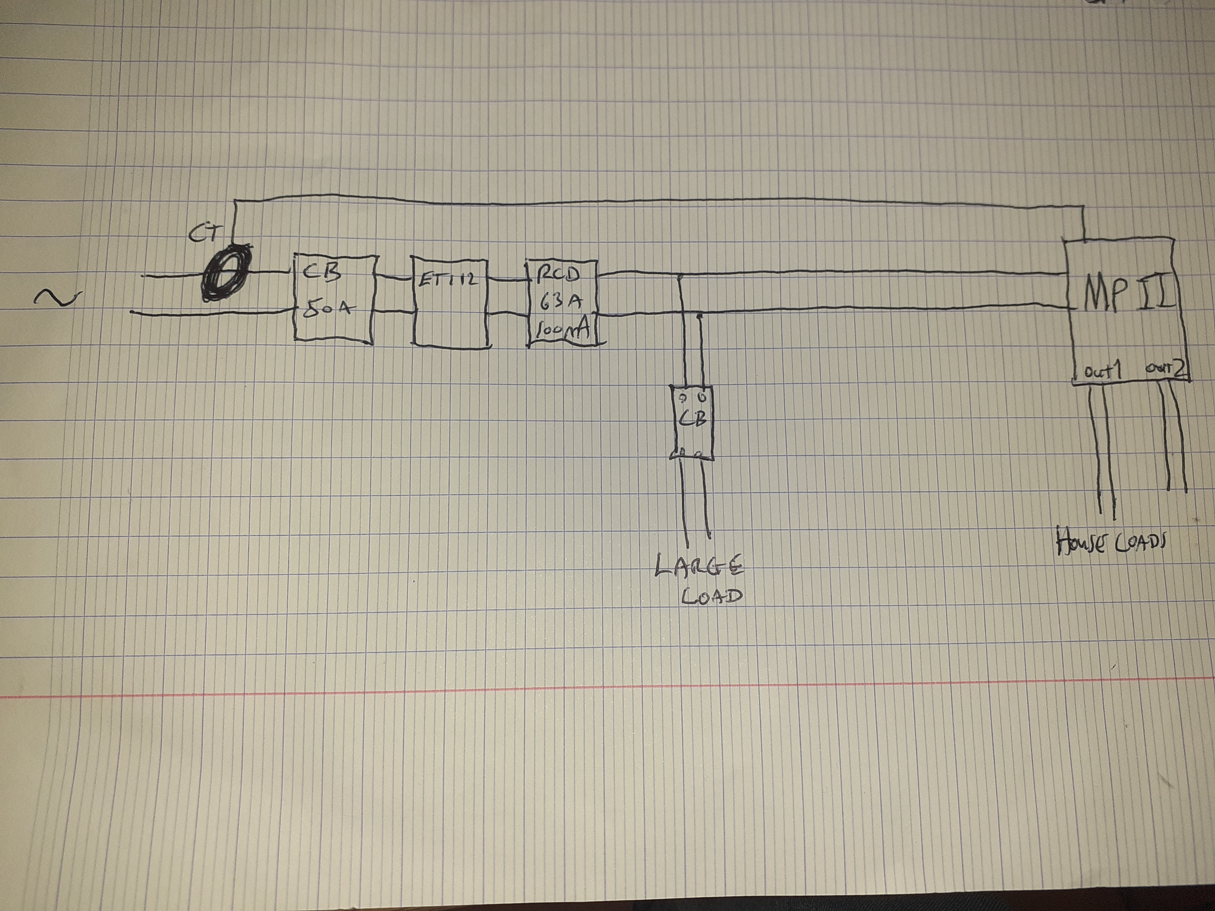
The CT is the first thing after the meter then: 50A main switch, EM112, RCD, at which point the cabling goes to MP2 and a separate, big, single load. The MP2 supplies all other loads.

The threads I have already seen on this issue tend to suggest that firmware updates would solve the problem but that is a good while before v. 496. I read that the big load is also a factor with error 24 but then this load is before the MP2 and should not be supplied via the MP2 in the event of a power cut.

Any ideas would be welcome.

Thanks.

Multiplus-II
2 |3000

Up to 8 attachments (including images) can be used with a maximum of 190.8 MiB each and 286.6 MiB total.

12 Answers
usernamepasswordbs avatar image
usernamepasswordbs answered ·

If it's not the firmware and it's not the check box that's not checked, what could it be ?

Is there a way to analyse the actual sequence of events in the MPII that leads to the error? The advanced data in the VRM seems to show it's not exactly the moment when the grid power came back on that the error occurred.

2 |3000

Up to 8 attachments (including images) can be used with a maximum of 190.8 MiB each and 286.6 MiB total.

usernamepasswordbs avatar image
usernamepasswordbs answered ·

Or is there a way to disable error 24 ?

2 |3000

Up to 8 attachments (including images) can be used with a maximum of 190.8 MiB each and 286.6 MiB total.

usernamepasswordbs avatar image
usernamepasswordbs answered ·

@Matthias Lange - DE It seems you're the man who knows about this sort of thing:

I have been through the official list of probable causes.

1. External current sensor is ticked in V.E.config, so not that,

2. Firmware is a recent version, so not that,

3. There is a large load connected but less than transfer switch capacity (load is 32A max) and as can be seen from the drawing, shouldn't be supplied through the MPII in the event of a power cut.

Have you got any ideas for a solution?


Sorry, I forgot to include the batteries in the diagram.

Sorry to make multiple posts about this but someone woke in the middle of the night to find all power out and their CPAP machine (a medical device) had stopped. The grid had actually reinstated itself but power to house loads (which passes through the MPII ) was blocked due to this error so we would like to find a solution if possible.

Thanks,20231111-154903.jpg


2 |3000

Up to 8 attachments (including images) can be used with a maximum of 190.8 MiB each and 286.6 MiB total.

Jason - UK avatar image
Jason - UK answered ·

@usernamepasswordbs Why are you using both a CT sensor and a EM112? You're doubling up on the recorded grid supply recording, assuming the EM112 is connected to your Multiplus. One or the other.

I used to use the CT sensor but then as my Multiplus only powers the loads on AC-Out, I realised I dont need to use it so I disconnected the CT sensor and fitted a ET112 so I can see the loads before the Multiplus.

Depending on the information you want to display in the VRM portal and if you want the multiplus to also supply the loads before the Multiplus (Grid Loads), that would define what meter or CT sensor is best to use.

Link before to my VRM portal, in the photos I have a schematic of my system which shows the location of my ET112. Previously I had the CT sensor on my incoming tails.

https://vrm.victronenergy.com/installation/171934/share/db6807bb

10 comments
2 |3000

Up to 8 attachments (including images) can be used with a maximum of 190.8 MiB each and 286.6 MiB total.

daza avatar image daza commented ·
@Jason - UK wish my output was that stable it’s all over the shop
0 Likes 0 ·
Jason - UK avatar image Jason - UK daza commented ·
@Daza Whys is yours all over the place? The measurement or the actual current?
0 Likes 0 ·
daza avatar image daza Jason - UK commented ·

Multi output keeps jumping a hundred plus watts and still draws 10 to 100watts from the grid randomly wired Victron CT even when grid set point is -30, but even the shop remotes in and doesn’t know why it’s doing it.

0 Likes 0 ·
Jason - UK avatar image Jason - UK Jason - UK commented ·
@Daza The information displaied on VRM is a calculation of difference between the CT sensor and the ET112, not the actual current measurement because of any loads that could be on the AN-In side of the MP. The CT sensor has next to no latency but is not 100% accurate, whereas the ET112 is very accurate but has high latency. Because of this, you will always get in odd information provided on VRM.

I have my grid set to -30w, I have a ET112 grid meter and a Victron Multiplus II GX 5kva set to supply critical loads only (AC-OUT loads). On VRM, it says grid +100w then -100 and so on, but when I check my energy supplier app (octopus) my energy is between 0w and -60w. My advice, dont worry too much about the info stated on VRM related to ET112 / EM112 meters. The real info within the GX & MP is doing its best job at keeping to your grid set point.

0 Likes 0 ·
daza avatar image daza Jason - UK commented ·
Same with octopus but mine reads those figures not the VRM, I’m lucky if my HUD stays 0 for 10seconds even though the VRM is saying -7 or -10 very weired I’m wondering if I have a faulty CT I’ll remove the clamp tomorrow to check I can’t believe i haven’t checked that lol cheers
1 Like 1 ·
daza avatar image daza Jason - UK commented ·
@Jason - UK appears there is an issue with the unit Victon want it back to fix.


@usernamepasswordbs are we a 100% the CT is working? And could it just be a faulty multi I would be inclined to backup and firmware update to wipe the unit and just go through it again I know it’s a ball ache but could be a faulty multi.

1 Like 1 ·
usernamepasswordbs avatar image usernamepasswordbs daza commented ·
I will try that. I haven't seen any cases of the MPII being faulty, but older firmware versions can apparently be a problem but there could of course be a fault with the Multiplus. Only a Victron staff member could make that call I suppose.

I was hoping @Matthias Lange - DE would chime in but it doesn't look like that's going to happen.

0 Likes 0 ·
daza avatar image daza usernamepasswordbs commented ·
Not heard of any issues with the multi not covering base loads, but I must be lucky as mine doesn’t :( and only 6months old was doing it from the beginning but thought it was a frequency issue with the smart meter and I moved heaven and earth to get it change for a different make.


The shop you bought it from can request it as I’ve had them remote in for me and they can’t see any setting issues.


update and try as you will be asked if it’s on that latest firmware and told to update anyway May well just do it in your own time frame.

0 Likes 0 ·
usernamepasswordbs avatar image usernamepasswordbs daza commented ·
Probably right about updating the firmware but I will have to reinstall other stuff like my relay control system which is also on the Cerbo and I'm not looking forward to it !

The only firmware i've read about causing error 24 seems to be 2 or 3 year old versions and mine's not that old, maybe 6 months.

From what I've read the officially accepted causes are old firmware, unticked external CT box and large load which could be a problem although my large load is well within relay capacity and also not supplied via the MPII ACout.

0 Likes 0 ·
daza avatar image daza usernamepasswordbs commented ·
Yeah mate updating is a ball ache but if you save the assistant and anything else you’ve done it will be straightforward to put everything back.


but maybe do the assistant first and test it to see if it functions as it should

0 Likes 0 ·
usernamepasswordbs avatar image
usernamepasswordbs answered ·

The reason for using both is because the ET112 gives more accurate information to the VRM but unfortunately the response time when loads are switching on and off is very very slow, 20 seconds or so.

The ET112 is connected only to the Cerbo and it alone gives data for the VRM to record as far as I know. The CT is connected directly to the MPII as external current sensor which allows the MPII to react very quickly to load changes. Best of both worlds.

Having said all that, do you think that could cause this error ?

2 |3000

Up to 8 attachments (including images) can be used with a maximum of 190.8 MiB each and 286.6 MiB total.

Jason - UK avatar image
Jason - UK answered ·

@usernamepasswordbs I cant see how you can use both as the data would conflict with each other. The CT sensor replaces the built in CT sensor so the moment you unplug it, it switches back to measuring the current within the built in sensor. If the Multiplus is recording the grid from the EM112, it thinks the CT it is measuring is the built in one. By using the external CT sensor, I think the Muliplus is measuring what it thinks is the internal CT sensor but it is actually measuring the grid, therefore giving the unit the incorrect data. I would unplug the external CT sensor, reboot the GX device then see what it going on.

If the problem still persists, then we can look further into it but that to me sticks out as a notable issue and a potential data conflict.


7 comments
2 |3000

Up to 8 attachments (including images) can be used with a maximum of 190.8 MiB each and 286.6 MiB total.

usernamepasswordbs avatar image usernamepasswordbs commented ·
I could be wrong but if the "external current sensor" box is ticked in VE.connect then the MPII uses external CT to manage its voltage.


The ET112 on the other hand, is feeding data to VRM via the Cerbo (my MPII is not a GX so the Cerbo is a separate device) and its role is "Grid Meter" but it's not being used by the MPII for load management.


Therefore there is no conflict even if there is a slight difference in measurement, they are doing different jobs. Please elaborate if you think that is not correct.

0 Likes 0 ·
usernamepasswordbs avatar image usernamepasswordbs usernamepasswordbs commented ·
Another point to mention is that the MPII already has an internal current sensor so when you install a grid meter as well you are already using a CT and a grid meter together. Switching the MPII's internal CT for an external one should change only the position at which the current is measured.
0 Likes 0 ·
Jason - UK avatar image Jason - UK usernamepasswordbs commented ·

@usernamepasswordbs Not quite correct. The ET112 data is used my the multiplus to maintain your grid set point. For a short period, I was also using both. I has the ET112 correctly as my grid meter, but I also had the CT sensor connected and enabled.

whatsapp-image-2023-12-07-at-225057-5192336c.jpg

The above sketch was basiclly how I had my set up for a short while. The reason being so VRM reported my EV charger as a grid load, but with power assist set to zero, and the CT sensor located in the location shown, the Multplus, whilst grid connected supplied DB2 & DB3 because by having the external CT sensor fitted, that is the point of which the Multiplus measures the power in, combined with any PV, and battery power being inverted, the 'critial loads shown on VRM is a calcualtion between CR sensor, inverter, and PV. Grid loads was a calculation between the external CT sensor and the grid meter, with the grid set point set to -30W. This may not have been how it was meant to be set up at the time but that is the result I got from that arrangement. The moment I unpluged the CT sensor, the Multplus would only supply the loads on the AC out. Regardless, VRM showed critical loads as the total from DB2 & DB3. This affected both VRM and how the Multiplus operated.

If I had the CT sensor and the ET112 in the same location as you have, because of the differences in accuracy (one being s shunt, the other being a CT sensor) and the difference in latency, the CT sensor would be fighting the ET112.

CT sensors can only measure the current, not the voltage.

0 Likes 0 ·
usernamepasswordbs avatar image usernamepasswordbs Jason - UK commented ·

When you unplugged your CT did you change the setting in VE.config ?

I think the use of a grid meter with an MPII means there is a grid meter AND a CT involved. Whether the CT is external or internal is another question.

Are you saying ditch the grid meter altogether ?

0 Likes 0 ·
Jason - UK avatar image Jason - UK usernamepasswordbs commented ·
@usernamepasswordbs NOpe, it just defaulted to the internal CT sensor.
0 Likes 0 ·
Jason - UK avatar image Jason - UK Jason - UK commented ·

@usernamepasswordbs 'Are you saying ditch the grid meter altogether ?'
It depends on how you want your system to operate and what information you want reported in VRM.

The only reason I have a ET112 is so I can see my grid loads in VRM that take their power from the grid only, no other reason. I dont use my Multiplus to power any loads on the grid side/ AC-In side on the Multiplus any longer and my whole house is on the AC out of the Multiplus. My grid loads are only powered at the same time as my scheduled charge during my off-peak therefore with my grid set point at -30w is irrelevant when I have a load on the AC-In as its during my schedules charge, both pull from the grid at the same time.

If I wanted to power loads before and after the Multiplus, but not care how the loads are reported in VRM, then I would ditch the ET112 because of how slow it is, and just you the CT sensor on the incoming supply. You only get a single total for all your AC loads but its more reactive.

'I think the use of a grid meter with an MPII means there is a grid meter AND a CT involved. Whether the CT is external or internal is another question.'

Incorrect, sort of. The multiplus will always use the internal CT sensor and it uses that to calculate the ac power in, inverter power out (or charger power in), and any PV. The calculation then tells you your AC loads on the AC-out of the MP. If you add a ET112 as a grid meter, the MP / VRM then calculates the loads before the MP, and the loads after.

If you remove the ET112, and use the CT sensor on your incoming mains tails, all you are doing is moving the measurement point from inside the MP, to outside the MP.

0 Likes 0 ·
usernamepasswordbs avatar image usernamepasswordbs Jason - UK commented ·

This is how I want my system to operate:

Operate so that a power cut/reinstatement does not cause the MPII to shut down "permanently" with error 24.

Simple as that.


0 Likes 0 ·
mjs500 avatar image
mjs500 answered ·

CT connected to multiplus wire type and plug in type ?

2 |3000

Up to 8 attachments (including images) can be used with a maximum of 190.8 MiB each and 286.6 MiB total.

usernamepasswordbs avatar image
usernamepasswordbs answered ·

CT connected to Multiplus: wire type (3 pin plug with 2 wires from CT plus one empty pin).

2 |3000

Up to 8 attachments (including images) can be used with a maximum of 190.8 MiB each and 286.6 MiB total.

mjs500 avatar image
mjs500 answered ·

ok not plug in type good

2 |3000

Up to 8 attachments (including images) can be used with a maximum of 190.8 MiB each and 286.6 MiB total.

daza avatar image
daza answered ·

For the CT clamp don’t tick external, it’s still seen as an internal MP sensor, once you tick external you will stop getting measurements from the CT. Take off the CT without changing anything and see what happens, just been playing around with this last night too just to check my CT which works :( @Jason - UK

Thats Strange as even if my ET112 is wire to the grid and I isolate myself from the grid it does not shutdown the critical load and the multiplus continues to function as it should no errors it only displays no grid on the VRM which you would expect. This is with my CT disconnected.

2 |3000

Up to 8 attachments (including images) can be used with a maximum of 190.8 MiB each and 286.6 MiB total.

usernamepasswordbs avatar image
usernamepasswordbs answered ·

I could try that but it must be said that one of the official causes of error 24 is apparently installing an external CT but NOT ticking the box in VE.config.

My system supplies the critical loads from the battery during a power cut as it should but when grid power is reinstated, the error occurs and all loads are cut and the battery just idles.


3 comments
2 |3000

Up to 8 attachments (including images) can be used with a maximum of 190.8 MiB each and 286.6 MiB total.

daza avatar image daza commented ·

img-4411.png
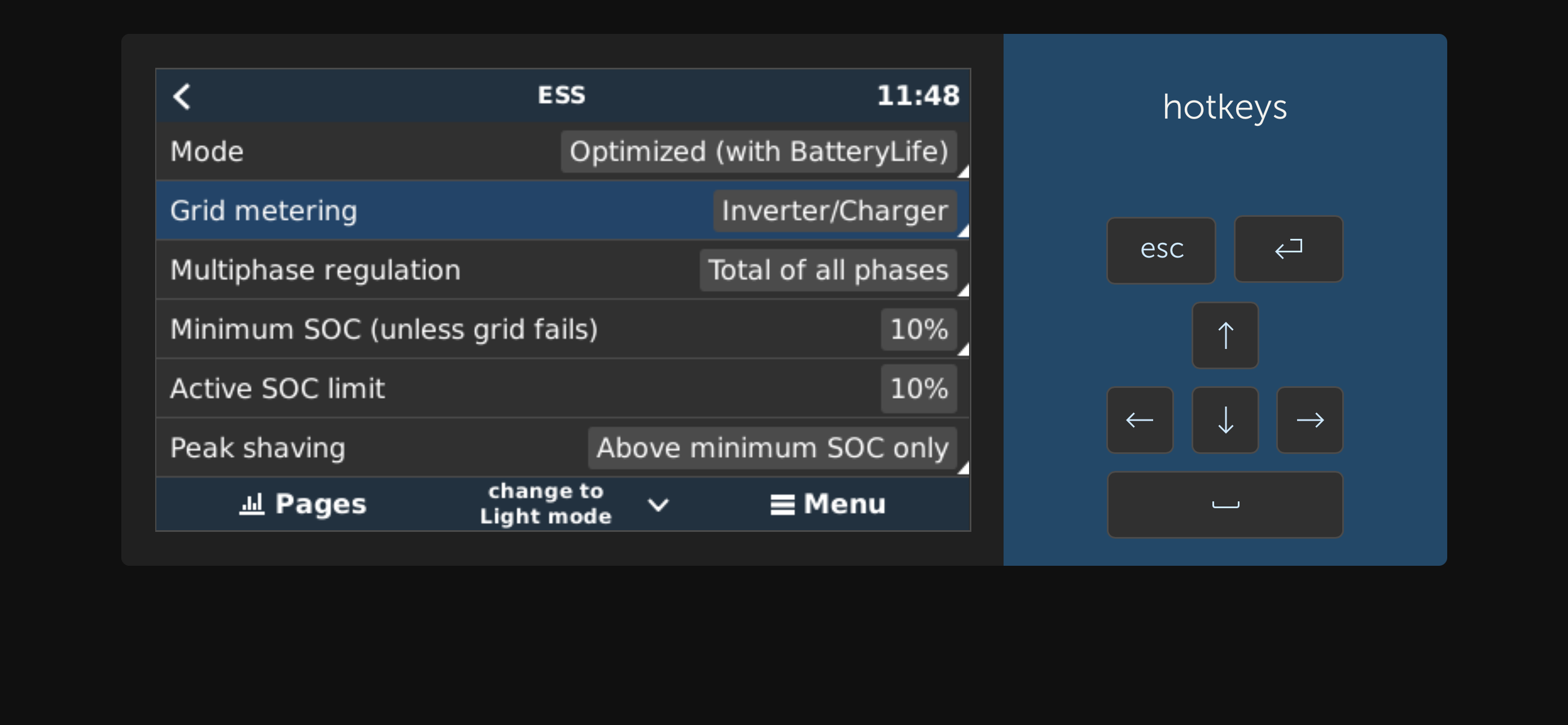
Was referring to the GX part I can’t remember what my VE config is set to but I’m pretty sure I didn’t tick it.

1 Like 1 ·
img-4411.png (300.1 KiB)
usernamepasswordbs avatar image usernamepasswordbs daza commented ·
In Venus settings mine is set to "inverter/charger" as well.
1 Like 1 ·
Jason - UK avatar image Jason - UK commented ·

@usernamepasswordbs Several other things to consider, do you have 'Monitor for grid failure' enabled? ESS Relay test completed?

1702033845219.png1702033956545.png


0 Likes 0 ·
1702033956545.png (42.8 KiB)
usernamepasswordbs avatar image
usernamepasswordbs answered ·

Monitor for grid failure: enabled. ESS relay test: completed.

2 |3000

Up to 8 attachments (including images) can be used with a maximum of 190.8 MiB each and 286.6 MiB total.