question

offgridvoltage avatar image
offgridvoltage asked

MPPT Overvoltage Warning / MPPT 450 Shutdown :(

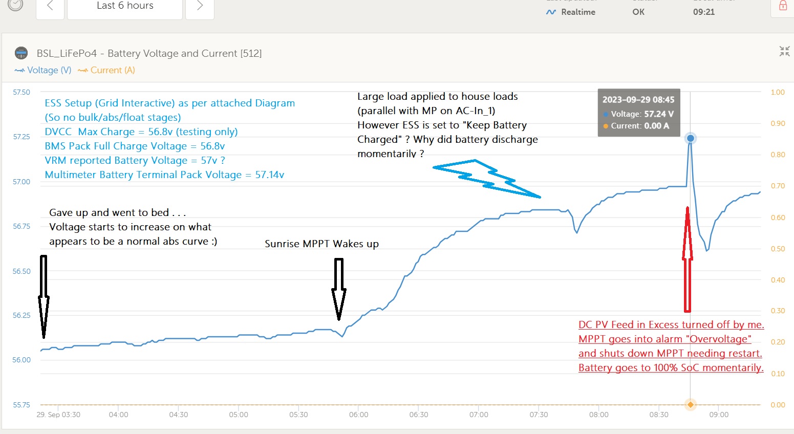
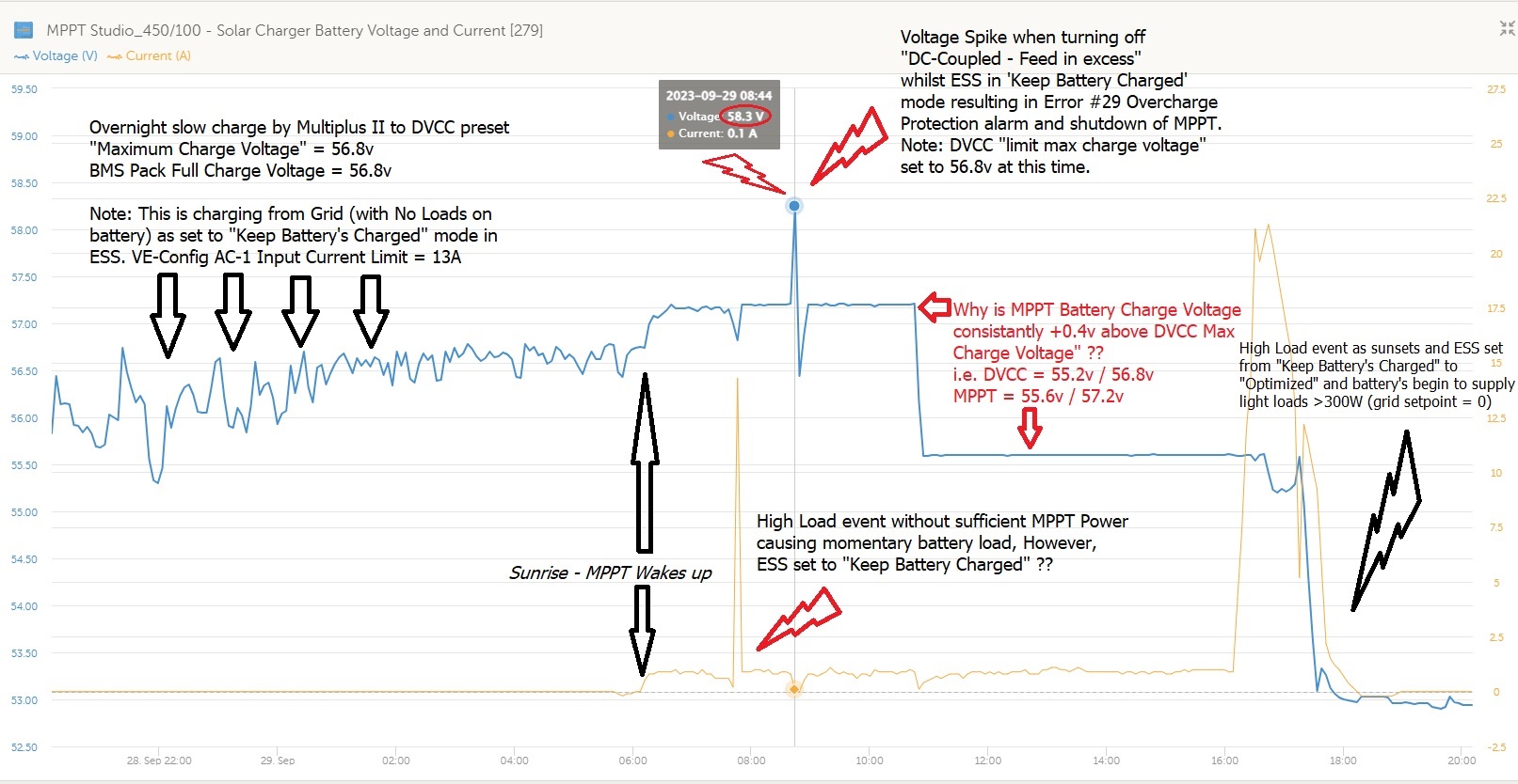
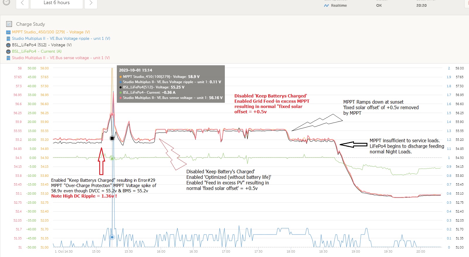
Hi Crew..... I've been getting Error #29 Overcharge Protection events whenever I turn off "DC-Coupled PV - Feed in excess" within my ESS environment.

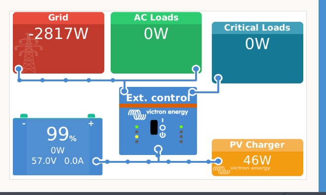
The Charge Voltage is seen to spike, then the Overprotection occurs and the MPPT stops charging and needs to be restarted after the event is cleared. Note: ESS is set to "Keep Battery's Charged".

See attached VRM Charts etc...

Is this a case of the MPPT not ramping down quick enough for the BMS, and therefore the BMS triggering a high cell voltage or something ? If so.... How do I prevent or negate this in the future ? (besides just never turning off 'Grid feed-in')

My panels Voc are well within voltage specs for the MPPT, so I don't believe this is a factor.

In times of excess solar being fed back to my home and grid, I sometimes need to limit the power and/or turn off this feature due to limited AC cable size feeding back from my Multiplus to my MCB and grid export limits etc.

What are the recommended BMS settings for Cell OV Alarm / Protect / Release & Delay time ?

Setup>>

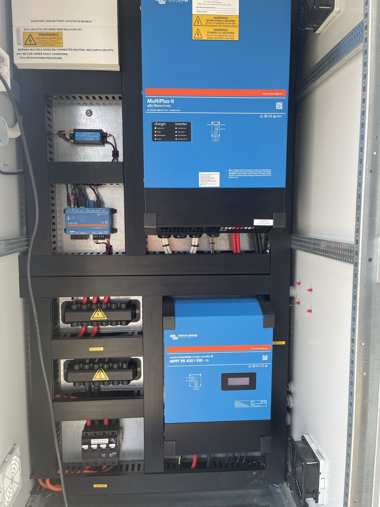
Multiplus II 48v 8K/110 230v (via VE.Bus)

DC-Coupled 14x Kookuburra 415w Panels (5.81 kW) (7S2P)

MPPT RS 450/100 Tr (via VE.Direct)

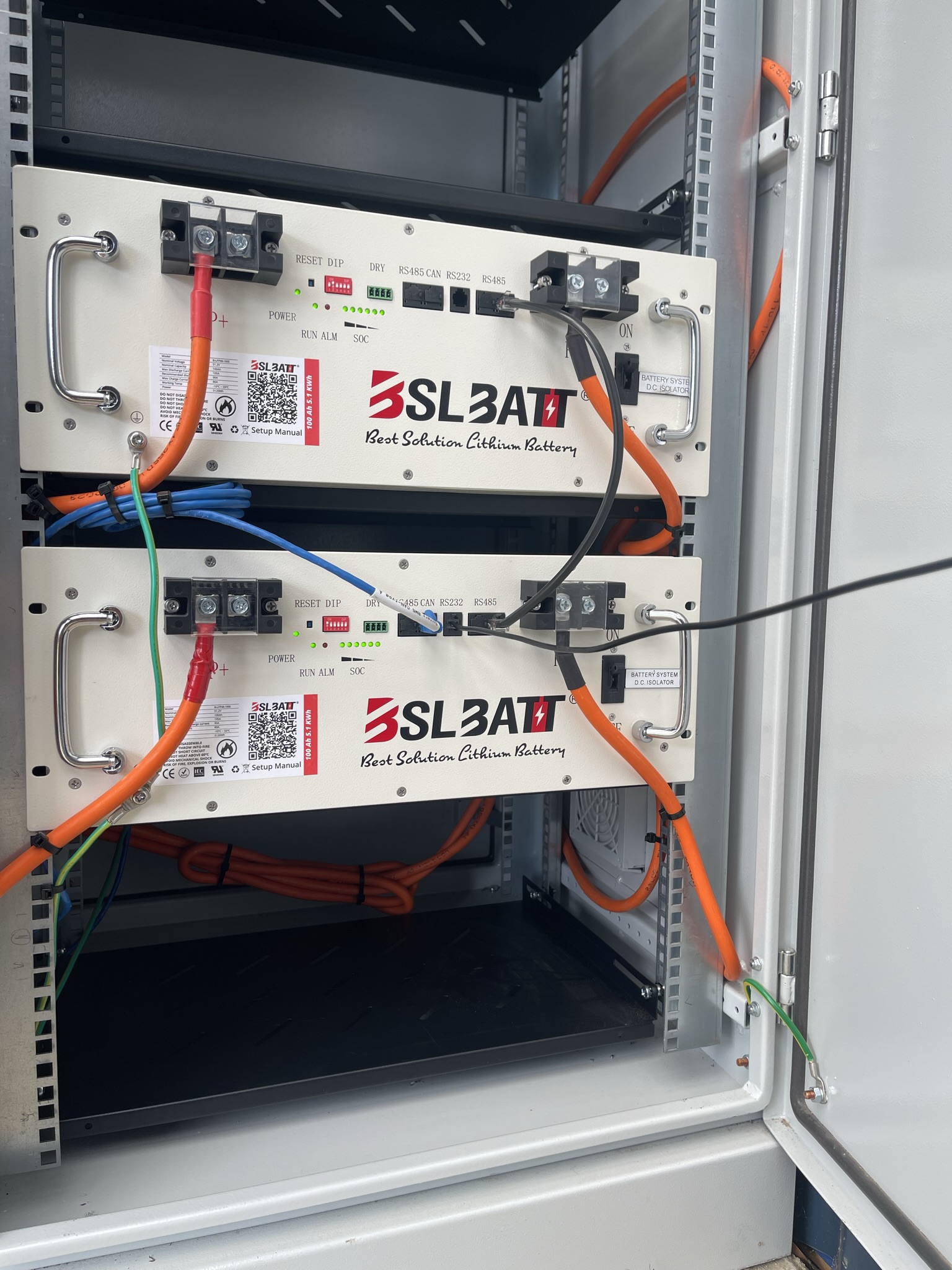
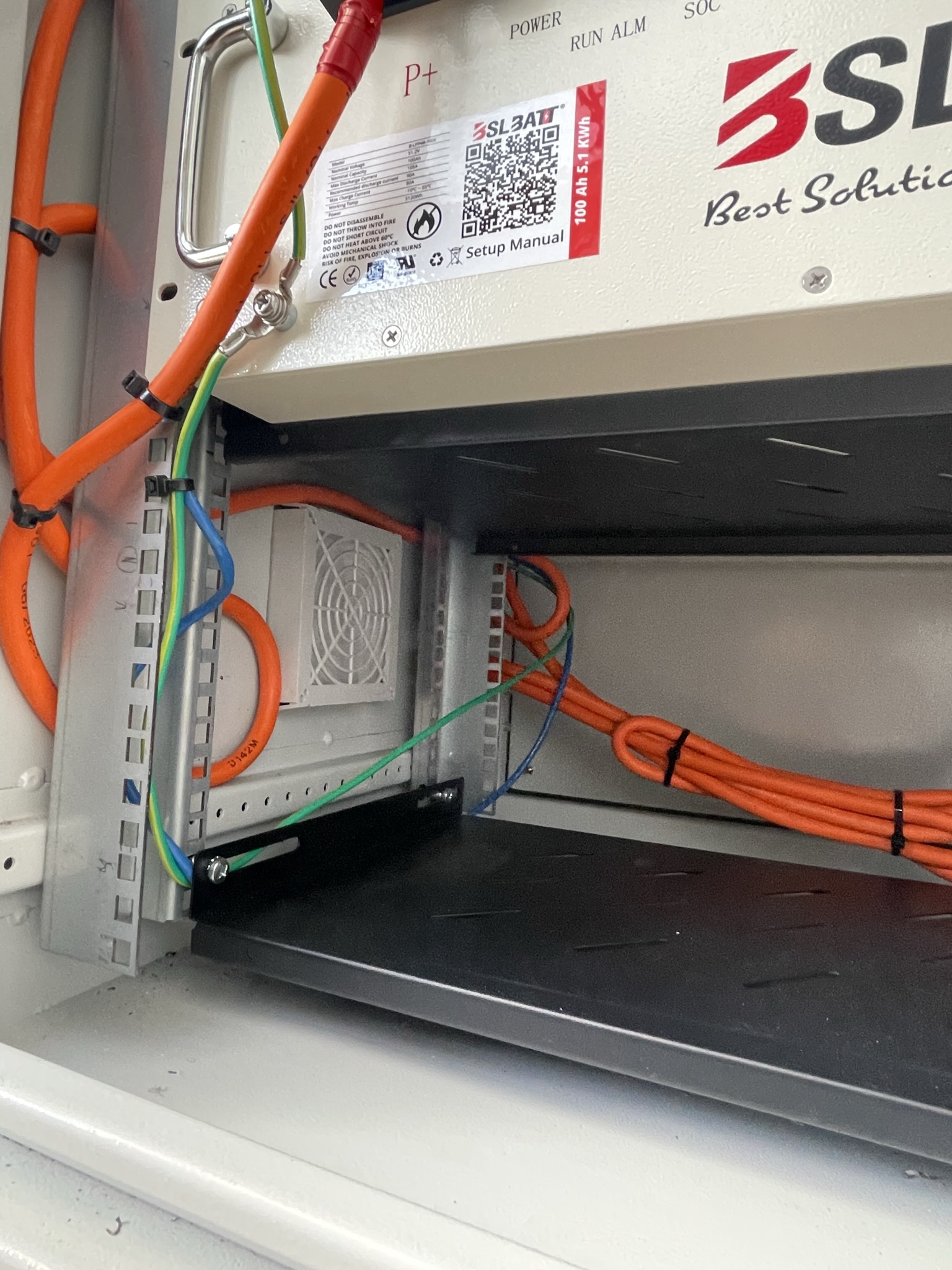
2X Parallel BSL LiFePo4 48v 100 Ah 5.12 kWh Batteries (via CAN-Bus)

Cerbo GX

Configured on a rear studio (with sub board) and grid connected via the main switchboard using the Victron Energy Meter (ET112) between grid / MCB

Also on the main switchboard is an AC-Coupled GoodWe MS-10kW Inverter (with HomeKit Smart Meter) fed by 18x 440w Jinko Panels (7.92kW) (9S2P)


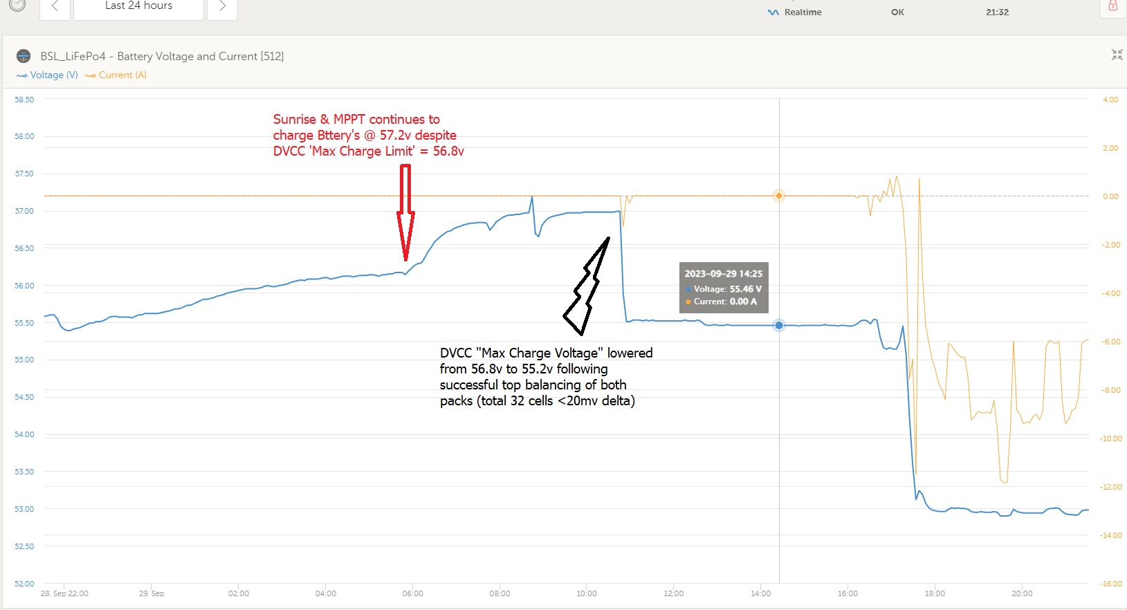
P.S. My current charge voltage is set to 56.8v as I'm attempting to top balance the new BSL battery packs, and not as a permanent charge voltage (normally 55.2v - as within my current ESS environment there is no such thing as bulk/abs/float of course)

overvoltage-vrm-batt-voltage-1.jpg

overvoltage-summary-1.jpg


Multiplus-IIESSMPPT SmartSolarlifepomppt overvoltage
2 |3000

Up to 8 attachments (including images) can be used with a maximum of 190.8 MiB each and 286.6 MiB total.

7 Answers
Alexandra avatar image
Alexandra answered ·

@OffGridVoltage

Can I assume you have followed the set up in the manual here?

In DVCC cap the charged voltage to just under the absorption voltage. 57v is too high for BSLs.

Of just set the battery to optimised with battery life and keep batteries to 100% SOC in case of grid faliure.

BTW BSLs do not like being kept at full charge.


You can check CCL DCL with a widget and battery min and max cells as well. But the real issue is the whole pack voltage is way too high way over 55v.

7 comments
2 |3000

Up to 8 attachments (including images) can be used with a maximum of 190.8 MiB each and 286.6 MiB total.

offgridvoltage avatar image offgridvoltage commented ·

Thanks for your reply Alexandra,

As mentioned in my post, I've only set the charging voltage to 56.8v temporarily in order to top balance the new battery packs. Normally I'd be using 55.2v (which they are now that balancing has been achieved with a 20mv delta between all 32 cells) Although I am unable to achieve 100% SoC, but that is the topic of another thread in another forum.....

Also as mentioned my post..... I was asking why the DVCC value of 56.8v was ignored and the voltage allowed to spike above 58v ? It's also curious why the charge voltage rose above the DVCC voltage also. I thought that the DVCC was a final governence of this Voltage ?

As per the manual, Yes I usually use the "Optimized" settings, however was allowing the battery packs to balance due to them being somewhat unbalanced previously.....which is why I was using "Keep Battery's Charged" to avoid load spikes and switching from charge <> discharge whilst balancing. So my question is why is it showing this behavior when it is switched to "Keep Battery's Charged" ? (why are the battery's allowed to momentarily discharge)

Cheers.


0 Likes 0 ·
Alexandra avatar image Alexandra ♦ offgridvoltage commented ·
Bsl don't have fast balancing.

I have over 20 in the field.

Also it would not be coping with the higher voltage you have programmed with.

You will be getting runaway cells.

Set it to the correct and recommended voltages leave on keep batteries charged.

Check the cell voltage levels in VRM advanced.

Do you have them daisy chained or individual to a bus bar?

0 Likes 0 ·
offgridvoltage avatar image offgridvoltage Alexandra ♦ commented ·

The battery's are cabled separately back to a bus bar using two(2) pairs of twin .25mm (4AWG) cable about 3x metres long. They are then wired from the bus bar to the MPPT & Multiplus II. Would it be better if they were cabled using both pairs to the Master Battery, with short jumpers to the parallel slave ? Could this be causing any serious voltage disparity at low or high current ? Thoughts ?

img-1590.jpeg

img-1581.jpeg

img-1580.jpeg

img-1578.jpeg

img-1577.jpeg


0 Likes 0 ·
img-1590.jpeg (716.4 KiB)
img-1581.jpeg (658.0 KiB)
img-1580.jpeg (779.9 KiB)
img-1578.jpeg (918.0 KiB)
img-1577.jpeg (646.8 KiB)
offgridvoltage avatar image offgridvoltage Alexandra ♦ commented ·

Yes, once I'd finished balancing both packs, I have returned the charge voltage to 55.2v within both DVCC and the BMS. They are now down to a 20mv delta between all 32 cells :) @Alexandra Do you know much about the BSL BMS type ? I can't find any onfo at all....

0 Likes 0 ·
Alexandra avatar image Alexandra ♦ offgridvoltage commented ·
We have opened every battery brand we have installed. At least in the beginning to know what we know from opening them up. It voids the warranty though.

They seem fairly generic like a lot of battery "manufacturers" today they share BMS with other brands. Maybe with shades of changes in firmware.

I don't like their balancing, a slower charge and longer absorption is usually the way we go with them. Because of the balancing system you can't let them run up high like that.

1 Like 1 ·
nickdb avatar image nickdb ♦♦ Alexandra ♦ commented ·
Its a PACE BMS
0 Likes 0 ·
offgridvoltage avatar image offgridvoltage nickdb ♦♦ commented ·
@nickdb Thanks Nick.... Can you plz throw up a link to a Data Sheet or any URL whatsoever ? I'm looking for an answer on why it offsets it's Pack Max Charge Voltage +0.5v and perhaps some info on calibration etc.
0 Likes 0 ·
offgridvoltage avatar image
offgridvoltage answered ·

These are the voltages etc obtained today.
overvoltage-vrm-mppt.jpg


overvoltage-vrm-batt-v.jpg


2 |3000

Up to 8 attachments (including images) can be used with a maximum of 190.8 MiB each and 286.6 MiB total.

nickdb avatar image
nickdb answered ·

Why are you trying to charge the batteries with a regime the manufacturer does not support and that would void your warranty? The certified and supported BSL setup is well defined, you have gone off the beaten path into unsupported territory.

As Alex has said, stick to the guide, you are only creating problems for yourself.

Charger spikes are often seen when the BMS is forced to disconnect and the MPPT has power to use and nowhere to put it. All usually config/install related.

2 |3000

Up to 8 attachments (including images) can be used with a maximum of 190.8 MiB each and 286.6 MiB total.

offgridvoltage avatar image
offgridvoltage answered ·

@nickdb As mentioned above, the packs were initially very out of balance within themselves and also between each other. This was causing many issues and not likely to just fix itself without an initial top balance.... The higher voltage charge was temporary for only one charge cycle and for the sole purpose of balancing both battery packs.... which was achived nicely down to >20mv delta between all 32x cells. Even though 3.55v/cell is not my normal charging voltage.... It worked great for this purpose and has now been set down to 55.2v (3.45v/cell) as described above.

So thanks for your input, but I believe I was fixing problems for myself, not creating them.

And btw, what is the "certified and supported BSL setup" exaclty ? There is very little info from this manafacturer, and zero info about their BMS. They do not respond to enquiries and offer little support.

If you're referring to both the documents made by Victron about these BSL battery's, they in fact directly contradict themselves regarding various voltages and often on the same page ?! I've found these 'guides' to be outdated, confusing and inconsistant at best !

i.e. the BMS configurable "Pack Full Charge Voltage" is consistantly offset by +0.5v when it is communicted to any Victron system ?! (so the BMS value of 55.2v appears as 55.7v everywhere within the Victron componants) Which one is the true value ? Why the offset ? Please refer me to where this is detailed on the "certified and supported BSL setup" you're referring to ?

I'm here to learn, so thanks again for your reply.

Cheers :)


2 |3000

Up to 8 attachments (including images) can be used with a maximum of 190.8 MiB each and 286.6 MiB total.

offgridvoltage avatar image
offgridvoltage answered ·

Another Error# 29 MPPT Spike - New Data

@Alexandra Do you think the DC Ripple here could be a factor ? Or is it a symptom.... ? (1.36Volts) due to my extra long battery cables (as per pics above)


overvoltage-vrm-custom.jpg


2 comments
2 |3000

Up to 8 attachments (including images) can be used with a maximum of 190.8 MiB each and 286.6 MiB total.

Alexandra avatar image Alexandra ♦ commented ·

@OffGridVoltage

DC ripple is the cause of many problems and early component death.

More of an issue with higher current.

A long undersized DC bus is definitely a problem.

On your above graph though remove the amps line and have one scale for all the voltages. It's pretty difficult to see volt drop etc with all the different scaling.

Also the bends in the cable will be messing with things as well. Cables have a bend radius for insulation reasons and adds resistance in those sections which will also add to DC ripple.


0 Likes 0 ·
offgridvoltage avatar image offgridvoltage Alexandra ♦ commented ·

Yes, my thoughts also. I was surprised when the Installers left it like that. This is a new area of electronics to me, as I usually dabble in RF radio / Aeronautics. But knowing DC as I do, that didn't look right (especially at high curent).

Do you think it may be a factor in the Error# 29 voltage spikes ? (if so why/how?) Or just a another concern....

0 Likes 0 ·
Fideri avatar image
Fideri answered ·

@OffGridVoltage

As for the offset issue, this is the response I got from BSL:

"The required charging voltage is 0.5 higher than the full charging voltage, so that it can be fully charged."

I don't know if that makes sense.

Fideri

2 |3000

Up to 8 attachments (including images) can be used with a maximum of 190.8 MiB each and 286.6 MiB total.

offgridvoltage avatar image
offgridvoltage answered ·

#Fideri Clear as mud ;) But that's not surprising for BSL they don't appear to be very good communicators post purchase.

2 |3000

Up to 8 attachments (including images) can be used with a maximum of 190.8 MiB each and 286.6 MiB total.