Documentation on the site
https://www.victronenergy.com/media/pg/The_Wiring_Unlimited_book/en/dc-wiring.html
part 4.6. Fuses and circuit breakers
Please show some light for the question about how to calculate the fuse(s) below related to the protection for the inverter from the batteries connection side.
In documentation there is advice to use Fuses placed in the positive cable.
For example we have the system like on the image battery_bank_01_fuse_2.png (attached).
1) Inverter 12v 3200w nominal continuous power (6400 surge power) -> 220v out
2) 12.8 LiFePO4 100AH (+bms) x 4 = battery bank (connected in parallel)
3) cable (Cu) connection length not more then 1m and cable cross-section 50 mm2 (thinking no need 70 mm2 but can use in case of need)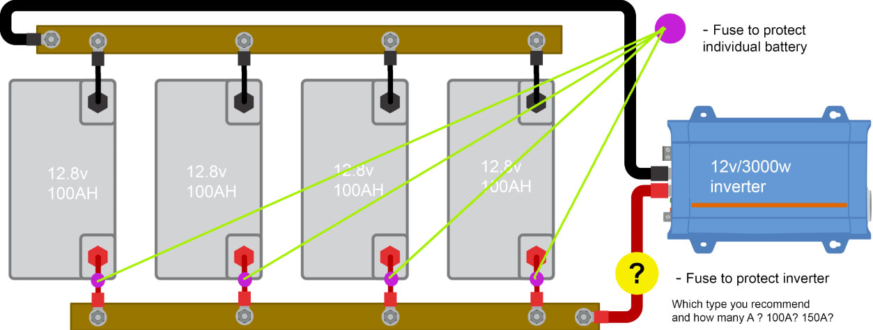
Question 1:
How to calculate the main fuse placed in the positive cable connection batteries bank to the inverter
(to protect the inverter from the batteries bank connection side (short circuit, etc) ) ?
With max load of the inverter we have:
3200w / 12v ~= 267A
6400w / 12v ~= 534A (surge)
Should we place the DC fuse 300A (12v) or what is better ?
/connection cable 50 mm2 (Cu)/ (if I need 70 mm2 cable (Cu) - will use it)
Question 2:
How to calculate the fuse placed in the positive cable for every individual battery before it connects to the general(+) busbar (5mmx20mm (Cu)) ?
(this fuse is protection of the individual battery in the batteries bank (short circuit, etc), right ? )
Should we place the DC fuse 150A (12v) or what is better ?
/connection cable 50 mm2 (Cu)/ (if I need 70 mm2 cable (Cu) - will use it)?
--------------------
Thank you for your time and advice.
asked
How to calculate the fuses to protect the inverter and individual battery in bank?
Fuses protect wires.
Wires should be sized to handle the continuous current. Surge is generally regarded as being so short, it's not considered in sizing.
Fuses should be 1.25X the current rating of the wire. This also helps give the fuse/breaker additional tolerance for surges.
3200W/12.8V/.85 = 294A (0.85 is for conversion efficiency)
The wires from the bus bars to the inverter need to be rated to handle 294A continuously. You'd need a 368A fuse (round up to 400A). Class T preferred due to the low resistance of LFP batteries.
The individual batteries are rated for 100A, so 100A wire and 125A fuse.
Fuses should be 1.25X the current rating of the wire.
What is the soure of that recommendation? At least in Germany this would not comply with VDE regulations. Of course, in other jurisdiction other rules may apply. Are you sure that it isn't the other way around?
I.e. first calculate the load (as you did), then choose a fuse which is higher than the maximum expected current (such that the fuse does not blow unintentional) and then choose a wire whose rating is 1.25 times *above* the rating of the fuse such that the wire is able to carry the current even if the fuse blows a little bit later than specified.
Remember that a fuse is a resistor that gets hot enough to melt when it blows. If the fuse is too close to the required current then the fuse will get very hot during service. This is why the fuse is rated at 1.25 times the required current. My 12V 300W inverter has a 400A fuse. The cable from the battery to the inverter should be rated on voltage drop, so may have a capacity higher than required. There was a case here a few months ago where someone had a fuse too close the the normal current and keep having problems with heat damage to the fuse holder.
That is exactly how it should be done.
The fuse is there to protect the wire from over current and the caliber of the fuse should always be lower than the current rating of the wire.
With the data provided by the topic starter, there's a maximum nominal discharge current of around 267A (~66.6A / battery module). (may need to evaluate if this is correct. Can each module handle this nominal discharge current? The victron superpack of this size has a nominal discharge current of 50A)
Therefore, he'd need at least a 25mm² cable with a 80A fuse per battery module.
The topic starter is also grossly underestimating the cable section needed to conduct 267A.
267A could be protected with a 315A fuse and would need a 150mm² or 2x50mm² cable
Assuming you install the cable in a ventilated tray with no other cables nearby.
As soon as you install that cable in a bundle with 1 other nearby cable, the section becomes: 1 x 185mm² or 2 x 70mm².
3 other nearby cables: 1 x 240mm², 2 x 95mm² or 3 x 50mm².
Cable length is not a factor here. A cable of 1m becomes just as hot as one of 10m. Only the voltage drops will be different.
Lastly you have to look at the interrupt rating of your fuse. You need to know the short circuit current of each battery module (something I'm missing, or not seeing, in the victron documentation of these battery packs) and add them together. Your fuse needs to have an interrupt rating (at the rated voltage) of at least that short circuit current.
If I may assume the Isc is comparable to a Pylontech module of the same size, you need to take into account 2,5kA per module, so 10kA in total here.