question

aegireon avatar image
aegireon asked

MPPT remains in float - rebulk offset not triggering

Hi there, we have two SmartSolar 100/50 MPPT controllers on a 12 volt system charging two Victron SmartLithium batteries. They do trigger a charge cycle every morning, however if the batteries become depleted during the day the rebulk is not triggering. The rebulk offset is set to 0.1 volt. Float is set to 13.5 volts. We've tried setting absorption to different levels (14, 14.2 volts) and it doesn't make a difference. Firmware is up to date. We are currently having to trigger new charge cycles manually by resetting to factory settings and then reselecting the correct battery type. We have ample solar power but it is not being used to keep the batteries charged. What could be causing this?

When a new charge cycle is triggered, the bulk phase ends very quickly whether the correct voltage is achieved or not, and the MPPTs go into absorption for a set amount of time, which is usually sufficient to charge the batteries.

Can anyone give me a definitive answer as to whether it's normal for the SmartSolar battery reading to be higher than the actual battery voltage? It seems to follow what it is currently outputting rather than the actual battery voltage. Is this correct? I'm not entirely sure how this feature is supposed to work and it would help us to narrow down the problem, as we're currently unable to figure out if it's the MPPTs themselves or a problem with our physical install.


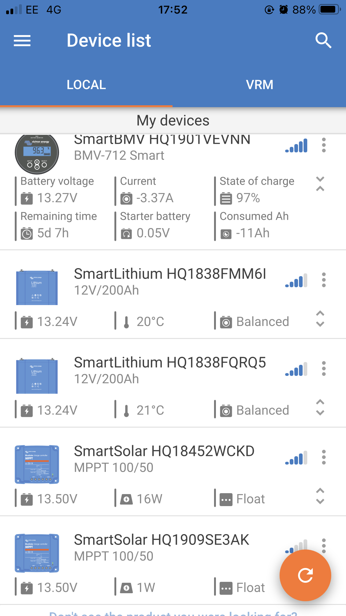
Example of failure to trigger rebulk:

img-2212.png


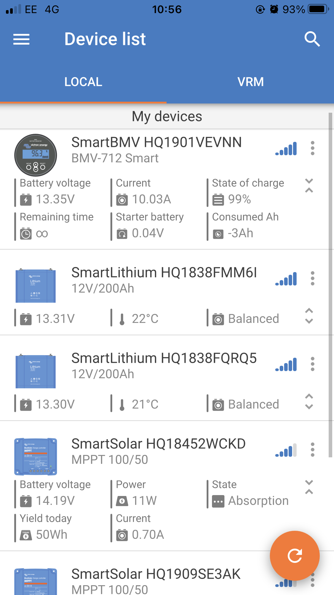
Example of going into absorption before batteries are full after resetting and triggering a new charge cycle:

img-2272.png


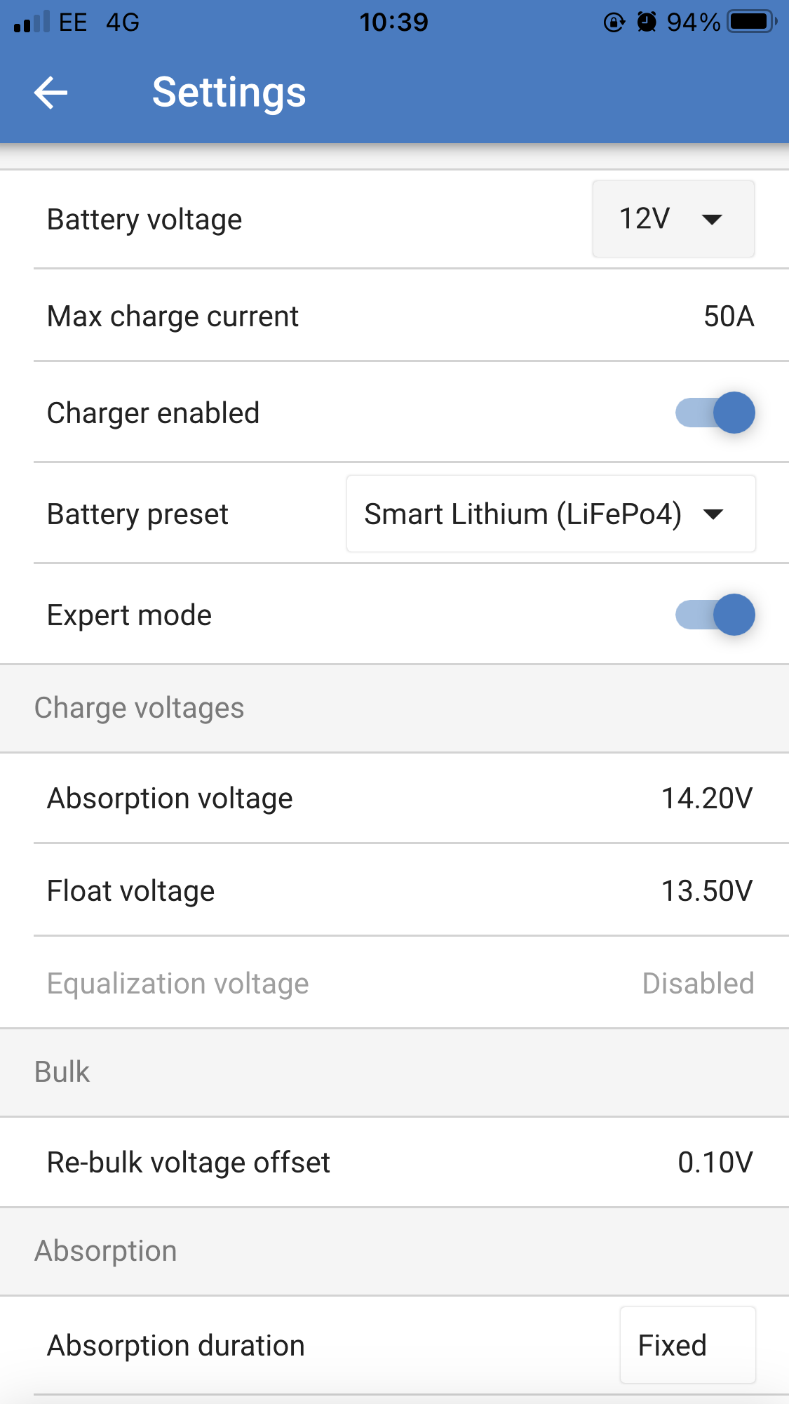
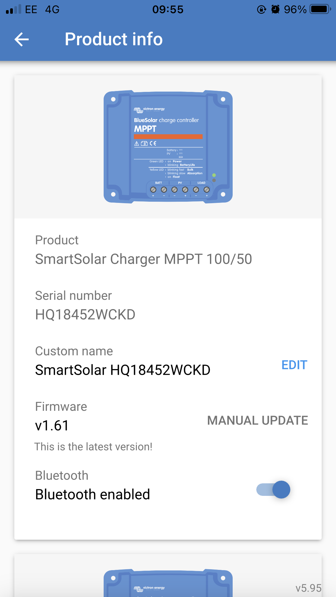
Current settings and firmware version:

img-2268.png

img-2265.png


Thank you in advance for any insight you can give.

MPPT ControllersMPPT SmartSolar
img-2268.png (277.9 KiB)
img-2265.png (328.0 KiB)
img-2212.png (454.9 KiB)
img-2272.png (474.7 KiB)
2 comments
2 |3000

Up to 8 attachments (including images) can be used with a maximum of 190.8 MiB each and 286.6 MiB total.

klim8skeptic avatar image klim8skeptic ♦ commented ·
@aegireon 0.9v difference between the mppt and battery would indicate deficient wiring/fusing between those two components.


KISS, measure the voltage drop across wiring/components.


1 Like 1 ·
seb71 avatar image seb71 commented ·
But in that case I think that the MPPTs should show lower voltage than the Smart Batteries and the BMV.

Unless they are completely disconnected from the battery.

1 Like 1 ·
4 Answers
klim8skeptic avatar image
klim8skeptic answered ·
@aegireon 0.9v difference between the mppt and battery would indicate deficient wiring/fusing between those two components.


KISS, measure the voltage drop across wiring/components.


3 comments
2 |3000

Up to 8 attachments (including images) can be used with a maximum of 190.8 MiB each and 286.6 MiB total.

aegireon avatar image aegireon commented ·
Hi there, we have found a voltage drop on the negative side, but it appears to relate to the fact we have a couple of lead acid starter batteries connected on the circuit that are taking some of the charge. Could this be causing a problem? Thanks!
0 Likes 0 ·
klim8skeptic avatar image klim8skeptic ♦ aegireon commented ·

@aegireon@Seb71 voltage drop of any sort is to be avoided.

Got a basic diagram to describe your system?

1 Like 1 ·
aegireon avatar image aegireon klim8skeptic ♦ commented ·
Thank you, your reply inspired us to try again to find the source of the voltage drop and this time we managed to find some loose connections on our BMS and tightening them up seems to have solved our solar problems.
0 Likes 0 ·
seb71 avatar image
seb71 answered ·

The BMV display is placed near the MPPTs?

As a workaround and also for synchronized charging, try using VE.Smart Networking.

https://www.victronenergy.com/media/pg/VE.Smart_Networking/en/index-en.html

The MPPTs should use the voltage value from the BMV.

1 comment
2 |3000

Up to 8 attachments (including images) can be used with a maximum of 190.8 MiB each and 286.6 MiB total.

aegireon avatar image aegireon commented ·
Thank you, smart networking did help. Ultimately the problem was a hard to find loose connection, but smart networking helped us to manage it.
0 Likes 0 ·
taylortops avatar image
taylortops answered ·

Do you have a circuit diagram? For one, I would switch the absorption period to auto and check the tail current in your BMV.

2 |3000

Up to 8 attachments (including images) can be used with a maximum of 190.8 MiB each and 286.6 MiB total.

aegireon avatar image
aegireon answered ·

Update: the problem was caused by a loose connection we had missed on the BMS on the negative side of the circuit which was causing transient voltage drops and the MPPTs responded by displaying a higher battery voltage than the true voltage. Thanks all for the responses.

2 |3000

Up to 8 attachments (including images) can be used with a maximum of 190.8 MiB each and 286.6 MiB total.