question

rocketman avatar image
rocketman asked

Fusing a pure DC system using 100/50

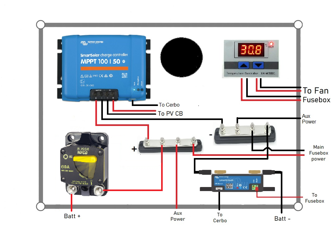
I'm designing a pure DC system using a 100/50 SCC. The manual says to use a fuse between 55-70A, looking at all the schematics on the Victron site, each one shows a fuse right off the battery and then a CB after the pos bus going to the SCC.

If I understand this correctly the schematics show a larger fuse right off the battery because of the draw from all the other loads on the bank (inverters). Since my system is a pure DC system and the loads are less than the recommended fuse for the SCC, can I just use a the one 60A fuse off the battery?


Thanks for your time and help.

fuses
2 |3000

Up to 8 attachments (including images) can be used with a maximum of 190.8 MiB each and 286.6 MiB total.

6 Answers
seb71 avatar image
seb71 answered ·

Don't connect all wires to the battery posts. Use busbars. Then you will have to size each wire and fuse according to the maximum current that wire is expected to carry.

2 |3000

Up to 8 attachments (including images) can be used with a maximum of 190.8 MiB each and 286.6 MiB total.

rocketman avatar image
rocketman answered ·

I am, see picture.


power-board-back.png (461.7 KiB)
2 |3000

Up to 8 attachments (including images) can be used with a maximum of 190.8 MiB each and 286.6 MiB total.

Justin Cook avatar image
Justin Cook answered ·

Fusing exists to protect the wire; if all of the wire you're using for every load and charger is suitable for 60A continuous current handling (10AWG fine strand or better) then that's technically fine to have one main 60A fuse at the battery. If any of your circuits use thinner wire, then that wire must be protected by a separate, lower-rated fuse.

1 comment
2 |3000

Up to 8 attachments (including images) can be used with a maximum of 190.8 MiB each and 286.6 MiB total.

matthias-nagel avatar image matthias-nagel commented ·

I tend to disagree that a single fuse at the battery is sufficient if everything is rated up 60A.

The battery and the MPPT are both able to _supply_ power and hence there can be more than 60A running towards the main fuse box.

Assume that there is heavy load on the consumers side (i.e. after the fuse box) or even a short circuit. Then 60A can be drew from the battery plus what is provided by the MPPT. This means it is possible that more than 60A flow into the fuse box.

The fuse at the battery primarily protects the battery from overloading (in both directions), the fuse does not protect the branch which goes to the main fuse box. It might happen that those wires carry more amps (shown above) and rhe battery fuse won't notice.


0 Likes 0 ·
rocketman avatar image
rocketman answered ·

Everything up to the fuse box which I forgot to show the other side of the board will be rated for 60A.


power-board-back.png

power-board-front.jpg


2 comments
2 |3000

Up to 8 attachments (including images) can be used with a maximum of 190.8 MiB each and 286.6 MiB total.

kevgermany avatar image kevgermany ♦♦ commented ·
Looks as if you're powering the Cerbo from the load terminals of the MPPT. If battery voltage drops and load cuts out, you'll lose the Cerbo functions and be blind. Better to power it from the busbar or fuse box.
0 Likes 0 ·
matthias-nagel avatar image matthias-nagel kevgermany ♦♦ commented ·
I assume you refer to the black line on the first page which comes out of the MPPT and is labelled "to Cerbo". From the position of the wire, this is seemingly supposed to be be the VE.direct cable (not a power supply). This connection re-appears as a blue line on the second sheet, labelled "to MPPT" and goes into the VE.direct connector.


The Cerbo GX is powered from the fuse box. There are another black and red line between the Cerbo and the thingy at the right which I now believe is meant to be the fuse box.

So this seems to be fine.

That is why I asked for a proper drawing. This pictorial drawing is not easy to understand, in particular because there are too many lines coming and going from nowhere which stop somewhere and then continue (or do not continue) somewhere else.


0 Likes 0 ·
seb71 avatar image
seb71 answered ·

Use fuses, not MCBs.

Also fuse the positive wire between the positive busbar and the MPPT Bat+ terminal. The MPPT is also a power source. Not just the battery.

Use gPV fuses on PV wires. And a PV disconnect switch.

5 comments
2 |3000

Up to 8 attachments (including images) can be used with a maximum of 190.8 MiB each and 286.6 MiB total.

matthias-nagel avatar image matthias-nagel commented ·
Why do you recommend fuses instead of MCBs?
0 Likes 0 ·
kevgermany avatar image kevgermany ♦♦ matthias-nagel commented ·
Many cheap ones that are unreliable, trip at the wrong rating. The one shown is an example.
0 Likes 0 ·
matthias-nagel avatar image matthias-nagel kevgermany ♦♦ commented ·

I cannot say anything about the one in the photo. But I wouldn't have used it either. (Personally, I am an all-ABB-man.)

But what you say is a truism. If one buys cheap crap, one gets cheap crap. That's true for everything even for fuses. I once saw fuses which did not trip at all, because they were basically a solid piece of metal.

Personally, I love MCBs. Moreover, In the jurisdiction of the US Coast Guard they are obligatory for safety critical loads (i.e. navigation lights, radio, etc.). So, personally I use them everywhere.

0 Likes 0 ·
seb71 avatar image seb71 matthias-nagel commented ·

If it trips, it is not a fuse.

A fuse burns and you have to replace it.

A nail is not a fuse, either.


The fuse rating must be chosen so that it protects the wire.

1 Like 1 ·
matthias-nagel avatar image matthias-nagel seb71 commented ·

Yes, sorry. This was inaccurate. A fuse does not trip, it burns or blows. (I am not a native speaker.) But this wasn't the point.

I agree with you in all points. The fuse or MCB must be chosen in accordance with the expected load and the wire rating. Nothing to discuss here.

I replied to kevgermany's argument against MCBs. Only because there are cheap, crappy (mostly China made) unreliable MCBs which trip too late or too early or not at all, doesn't count as a general argument against MCBs for me. This is a valid argument against a specific manufacturer and type of MCB.

My point was that this can happen with everything, even with fuses.

0 Likes 0 ·
matthias-nagel avatar image
matthias-nagel answered ·

Unfortunately, I have difficulties to understand your question as well as your picture. There are agreed technical symbols for drawing schematics. Maybe, if you would draw a proper schematic instead of usingg pictorial art style, I might be able to help you. For example, instead of showing a photorealistic representation of a main switch (first picture, bottom left), just use the proper technical symbol for a load-isolating switch.

In particular:

1. What is this "thingy" on right of the 2nd sheet supposed to be?

2. Where do neg bus and pos bus at the bottom, resp. top of that thingy come from? (There is no other terminal called by the same name, so at the moment these wires come and go from/to nowhere.)

3. Why is the auxiliary, red wire of the shunt labelled with "to fuse box"?! Normally, this connection is used to sense the voltage or temperature of the battery. Either way, it is normally connected to the positive terminal of the battery.

4. As someone else already wrote: The fuses must be chosen according to the rating of the wires. So without stating the diameter of the wires, it is impossible to size the fuse. Again, draw a proper schematic which includes this information. Maybe you might then even be able to answer your question yourself.

5. Where do "aux power" go to or come from? Is there another load or power source connected to? It seems that - whatever it is - by-passes the main fuse box. Without knowing what is there it is unclear what and where fuses are necessary.

6. Please provide a schematic of rhe "aux power" and the fuse box.

Bests, Matthias

1 comment
2 |3000

Up to 8 attachments (including images) can be used with a maximum of 190.8 MiB each and 286.6 MiB total.

kevgermany avatar image kevgermany ♦♦ commented ·
We're here to help people, not criticise because of a non standard drawing. Adding a photo in actually helps because we can see exactly what is intended.
1 Like 1 ·

Related Resources

Additional resources still need to be added for this topic