question

duncangardiner avatar image
duncangardiner asked

RosenPV 200A 10kw Powerwall setup with Victron RS 450/100 charge controller

Hi I am new to everything Victron.

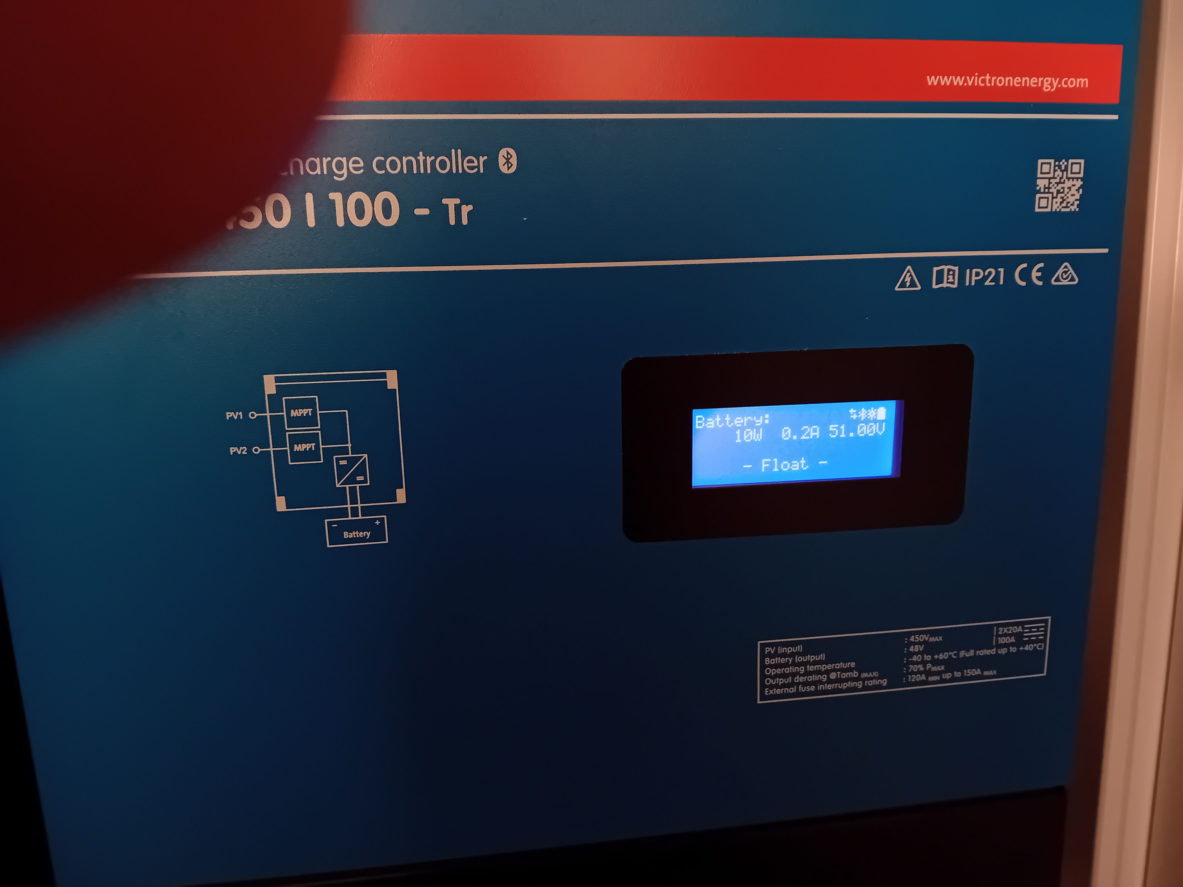
I have an eco system that consists of a MultiPlus II 48V 8000 inverter, a MPPT RS 450/100 Tr charge controller, and a CebroGX. I have 13 x 550w solar panels in 2 arrays (9 panels and 4 panels) one array per tracker channel on the RS 450/100. My Batteries (2 of) are RosenPV 48V 200A 10Kw Powerwall batteries.

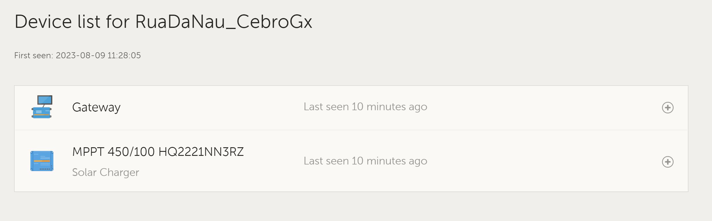
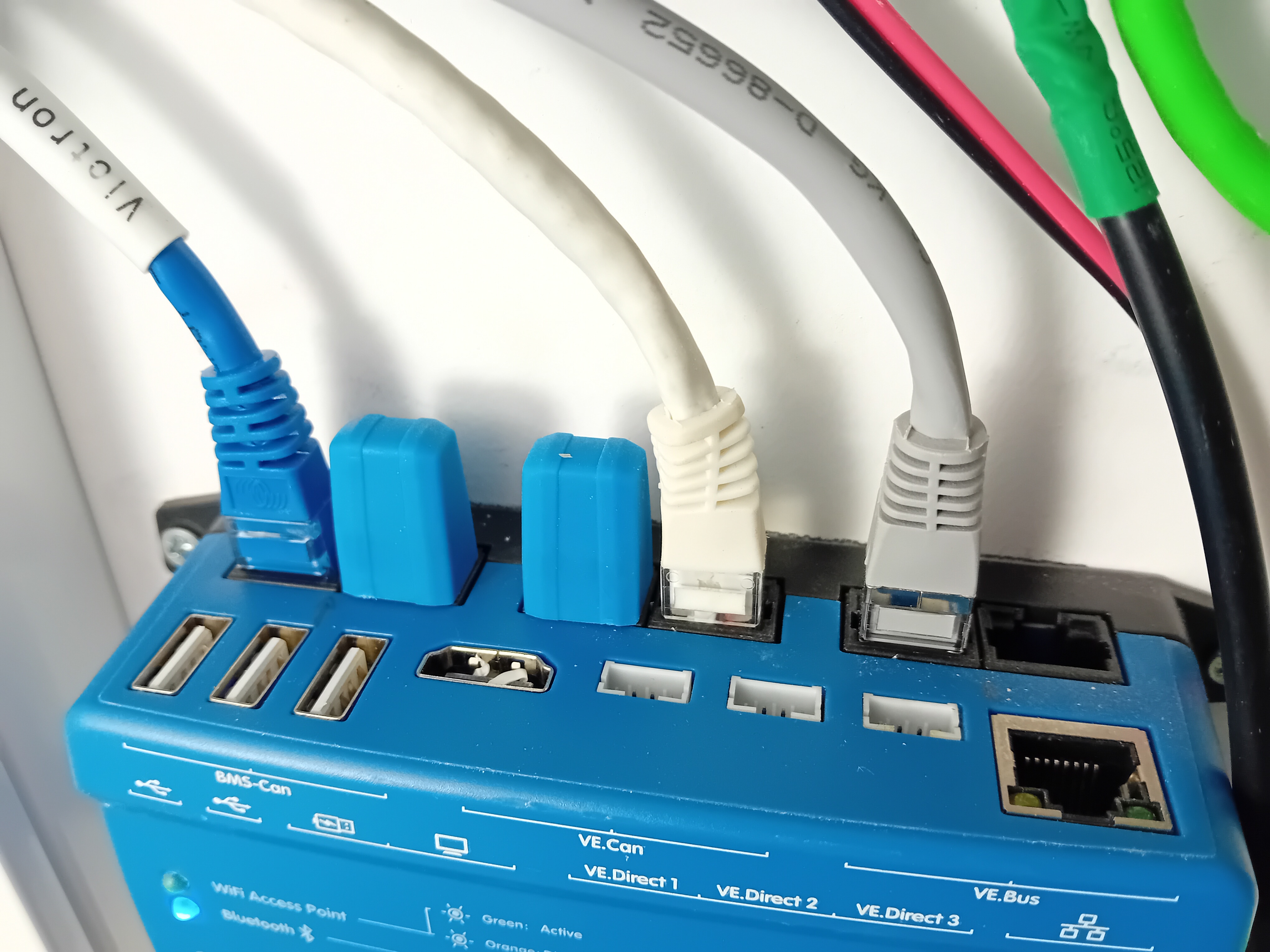
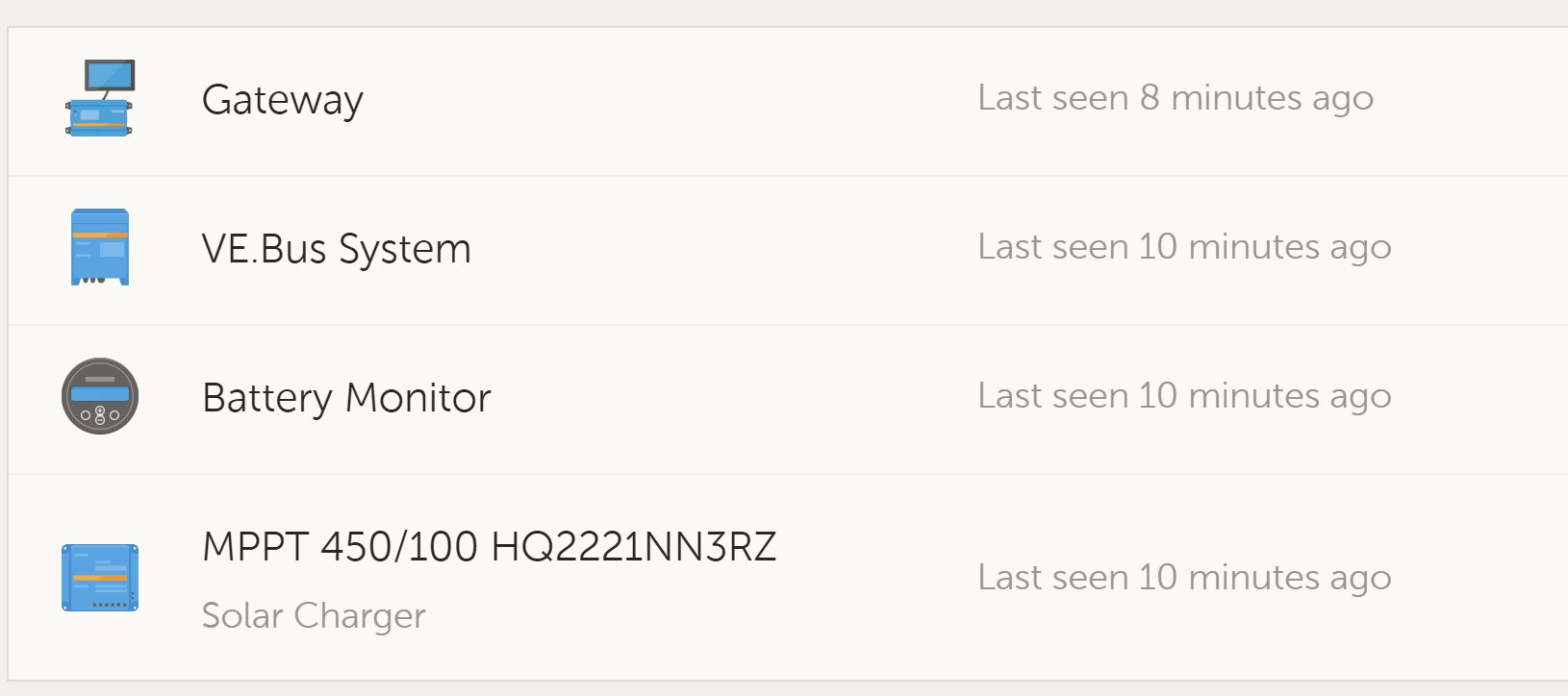
I am working my way through the configuration and setup. The CebroGx was easy-ish although I had a terrible time getting it to connect to my home network (attaching a LAN cable crashes my router, and it took ages before it would connect to the wifi). Now its connected I can see the RS and Cebro.

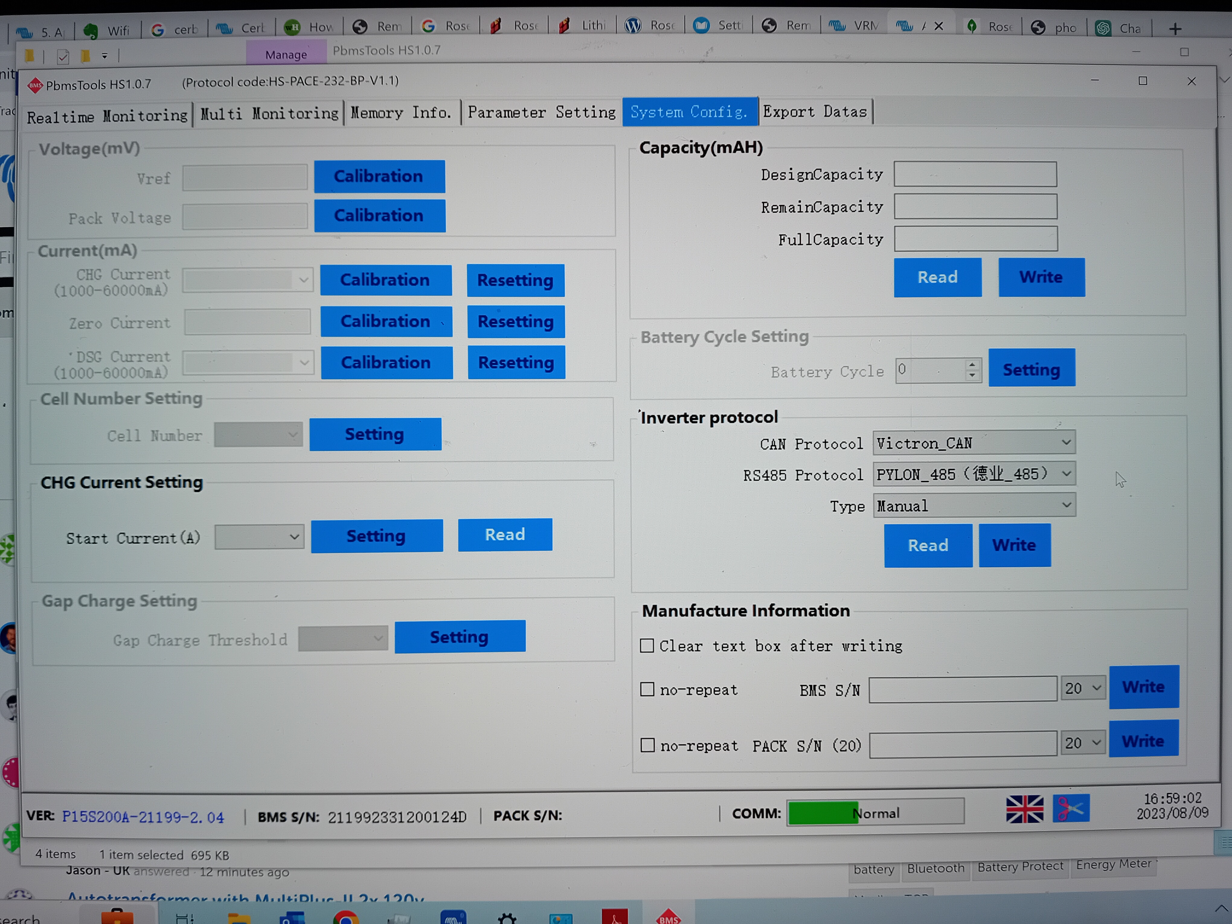
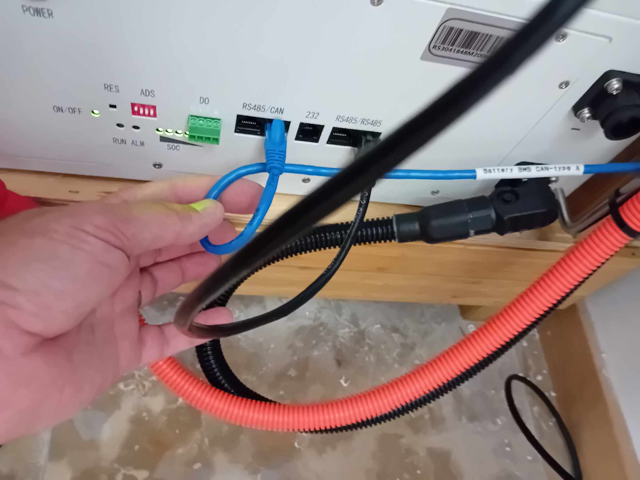
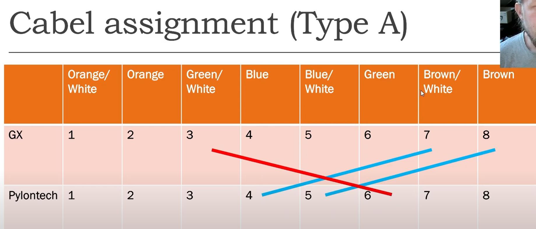
The Rosen batteries did not come with any documentation that helps with setup. After a few emails to their sales team they had an engineer connect to my Laptop and via the Pylontech BS software and a USB adapter to an 232 port configure the batteries individually. They've set the CAN interface to PylonTech CAN rather than the available Victron CAN. And could not answer me when I asked about the Victron terminators (where on the Rosen batteries could I add the terminator (as there are multiple RS485 ports available but only one CAN port per battery).

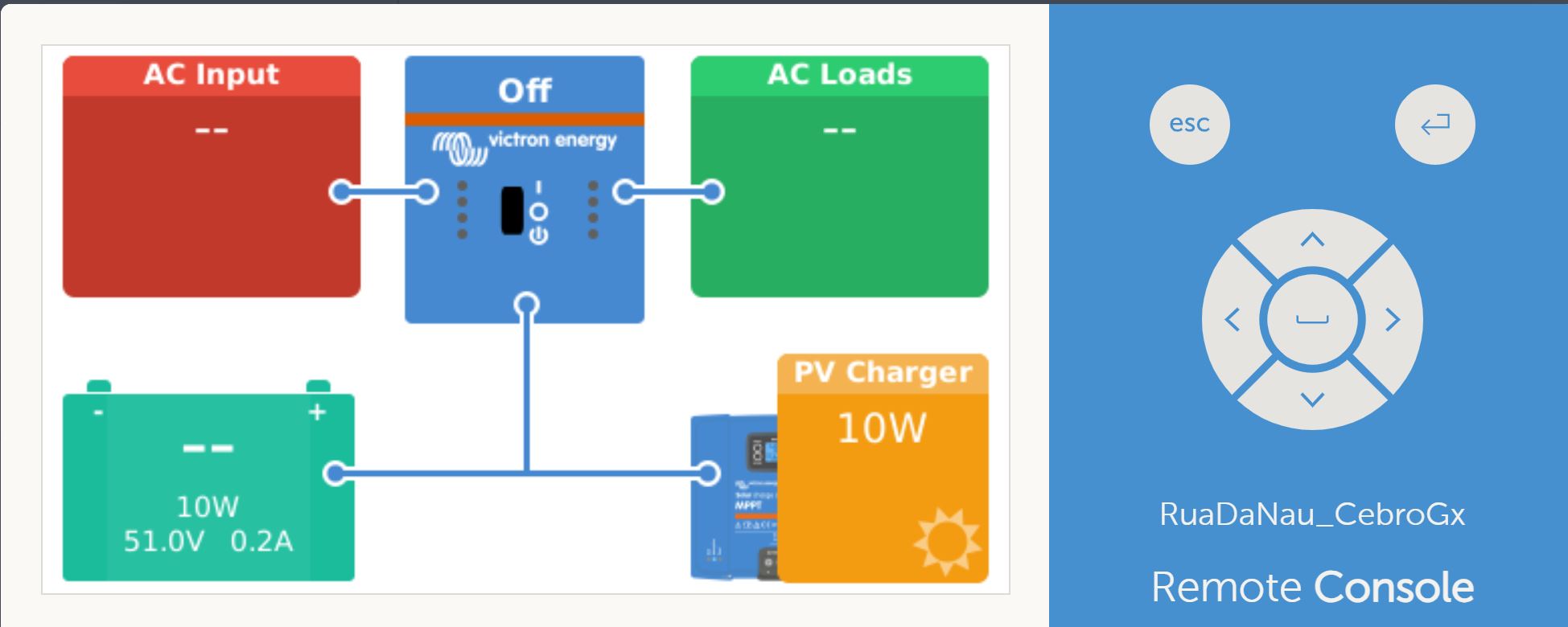
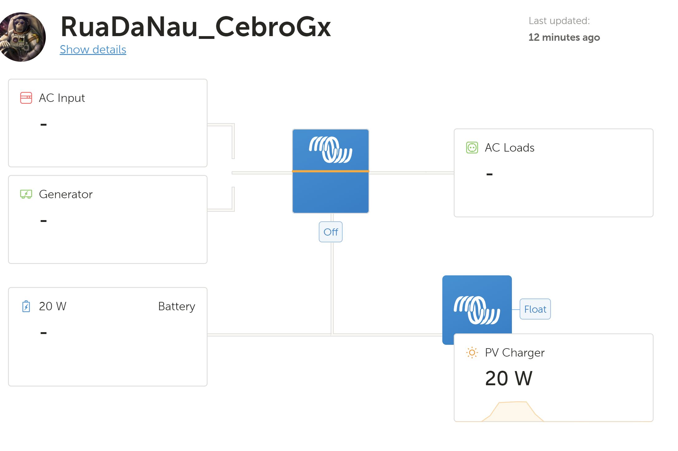
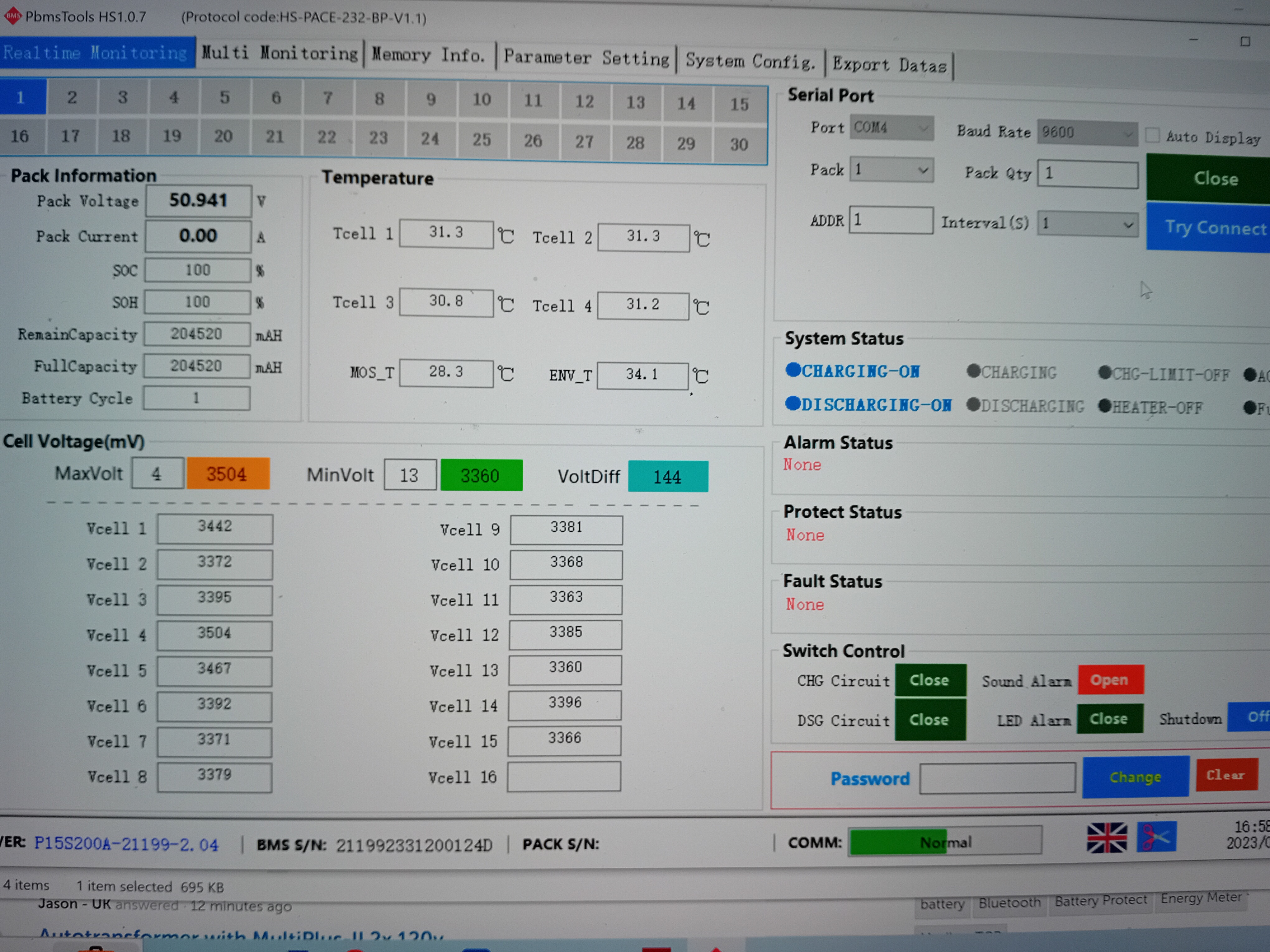
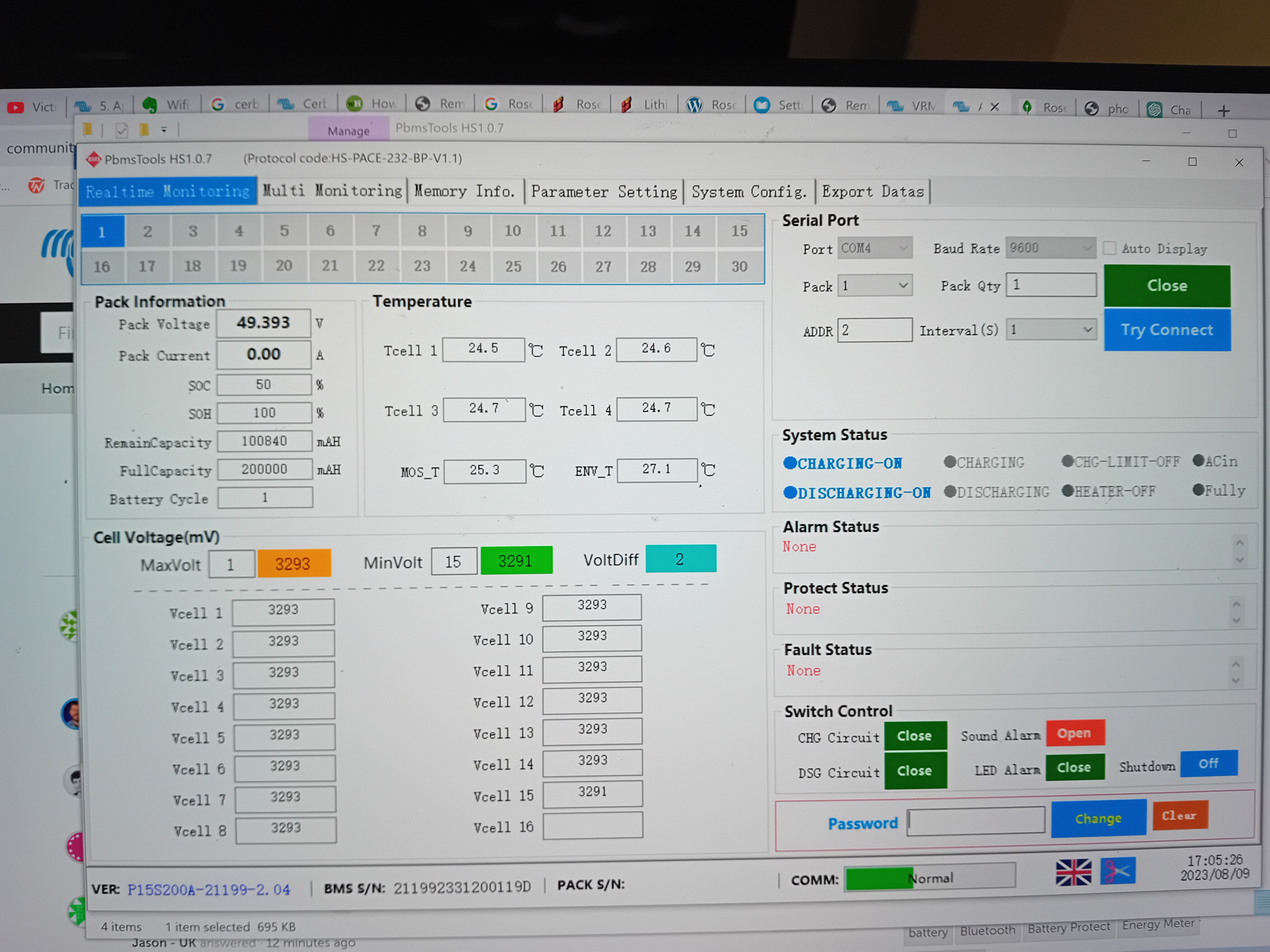
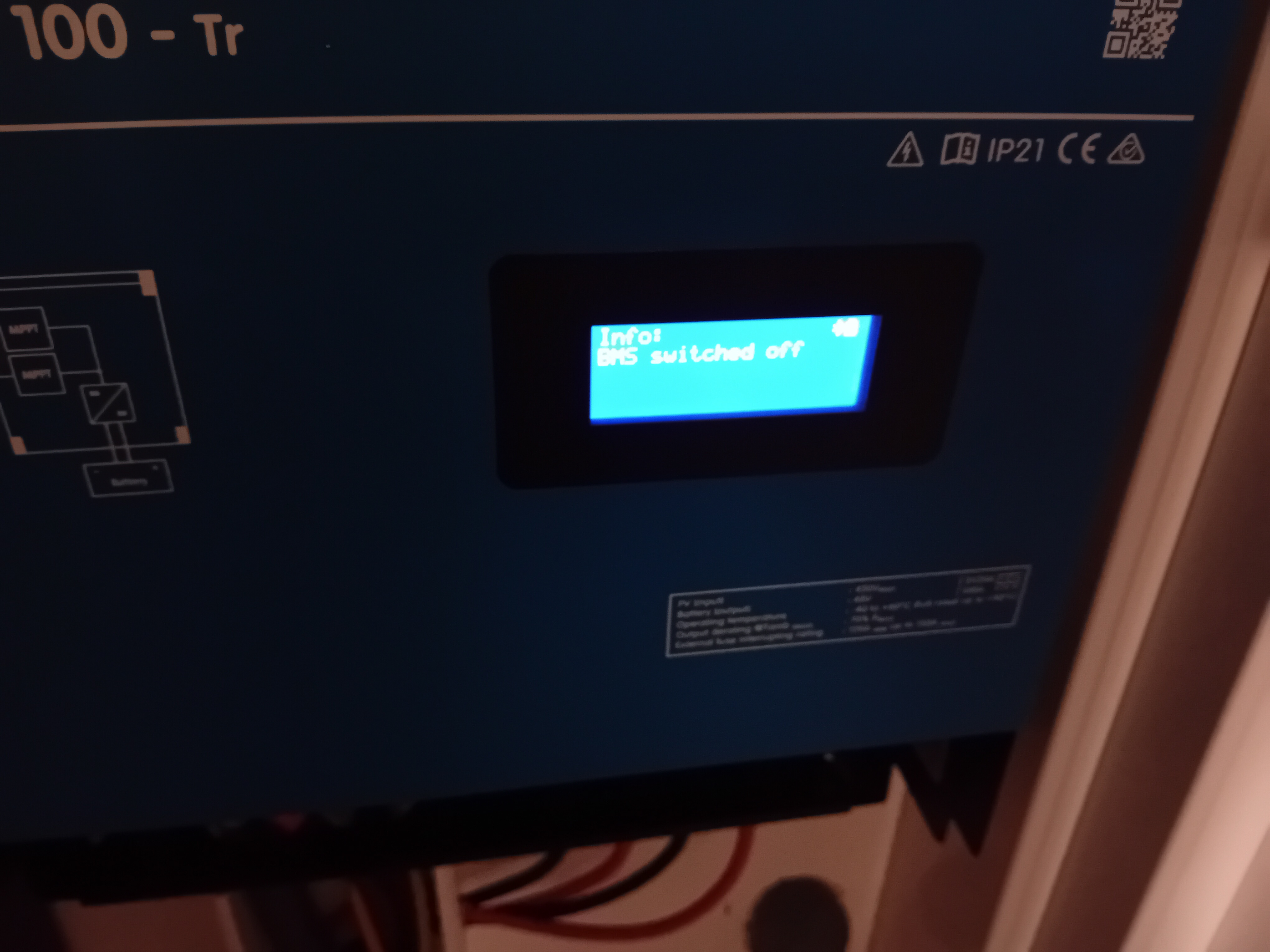
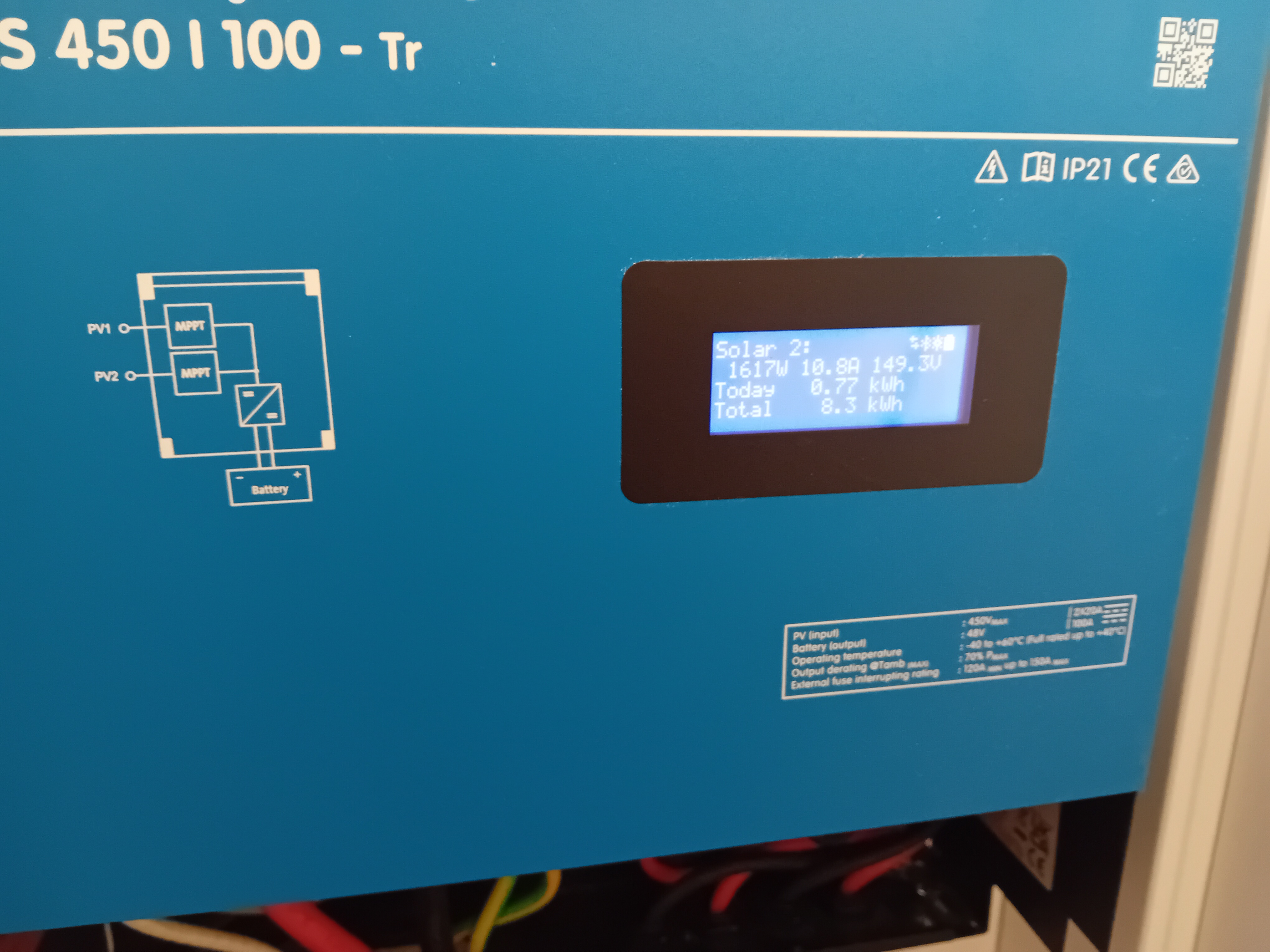
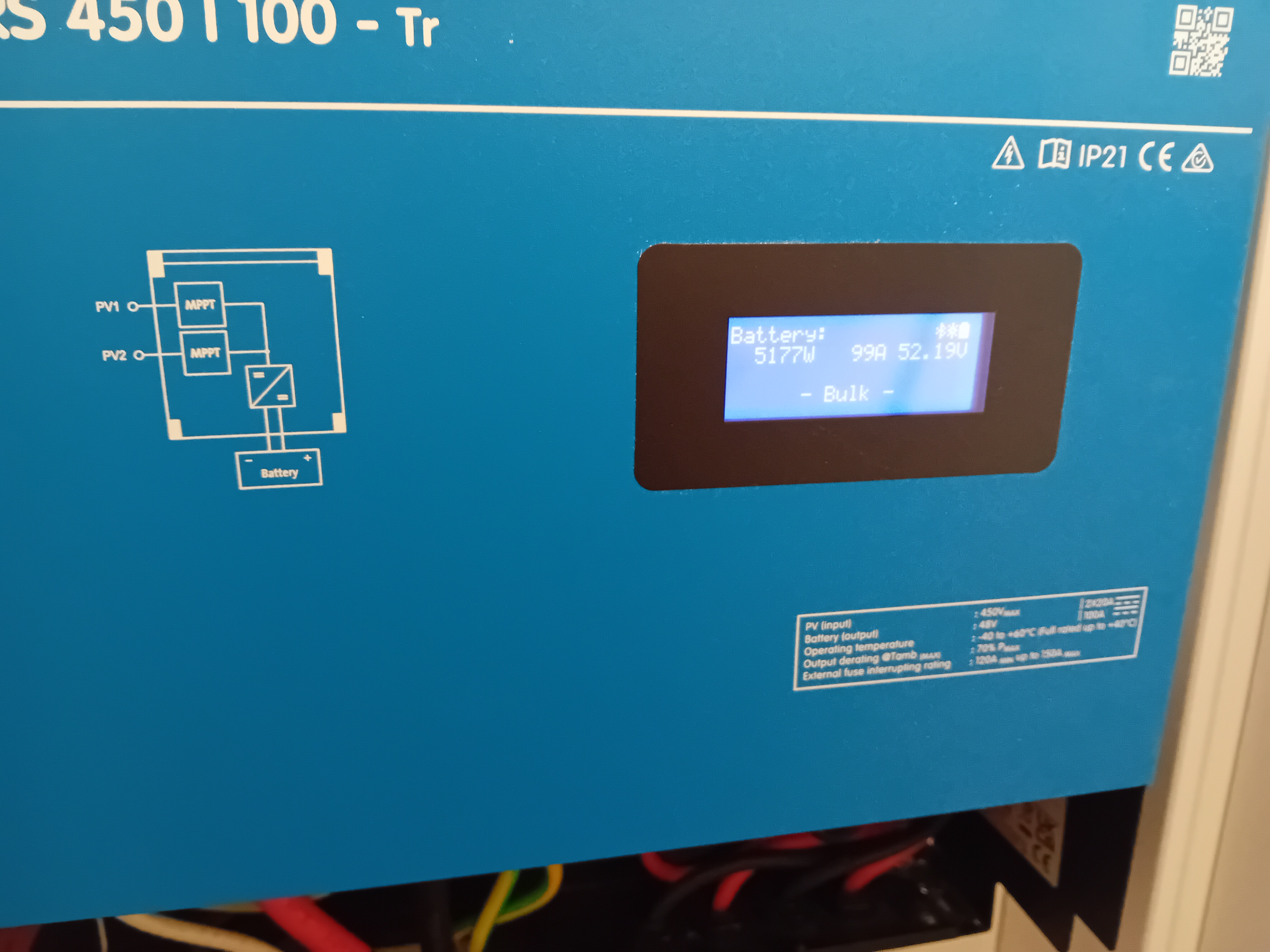
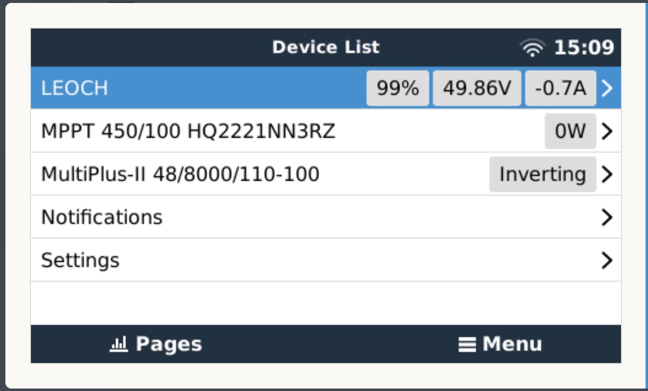
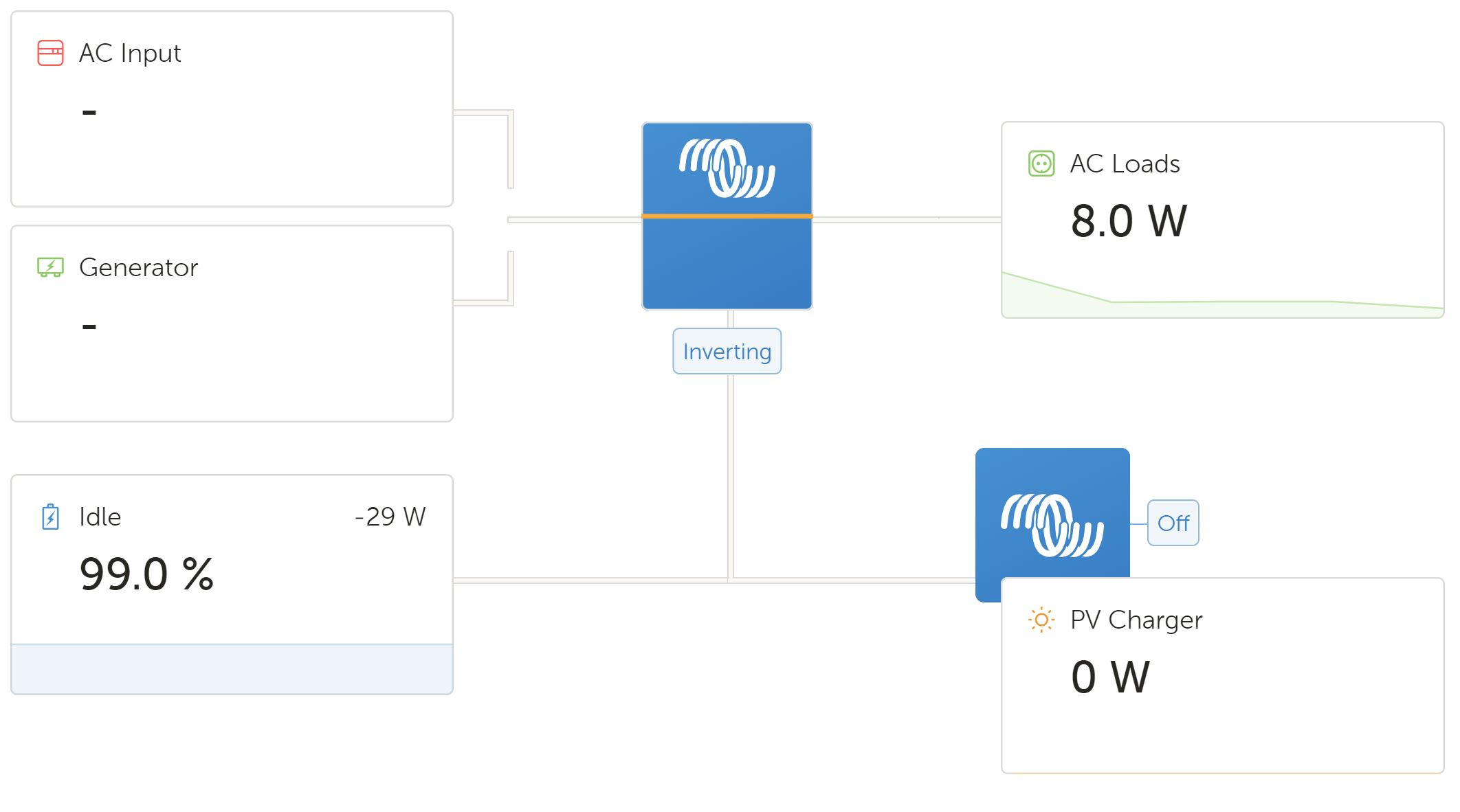
Right now I can see power being generated by the solar panels and the current being pushed to the batteries. But I can not see state of charge and therefore do not know if the charge controller can either.

Further I can not find anywhere the Absorption Voltage, Charge Voltage, and float voltage settings the RS 450/100 is asking me to set in any documentation offered by RosenPV.

So I have used settings from what looks like a Rosen bench test that displays Factory Voltage, Voltage at end of discharge, and Charging Voltage.

I have asked RosenPV the question, but as yet no answer (they are 13 hours out of sync to me in Portugal).

So I was hoping someone on here as set up the RosenPV 48V 200amp Batteries before and can offer me some guidance as to the correct charge settings and CAN configuration.


All answers greatly appreciated


Duncan

MPPT Controllers
2 |3000

Up to 8 attachments (including images) can be used with a maximum of 190.8 MiB each and 286.6 MiB total.

3 Answers
matt1309 avatar image
matt1309 answered ·

Hi @Duncan.Gardiner

I'm not familiar with this brand but I had a quick search and found some manuals that might help:

Rosen-48V-200AH-LiFePo4-Battery-Powerwall.pdf (energyserv.ie)

photovoltaikforum.com/core/attachment/228535-rosen-48v-lifepo4-battery-powerwall-user-manual-006-compressed-1-pdf/

Assuming i've found the right battery manual, it looks like the batteries are 15 cells each (similar to pylontech). I personally set absorption to 3.45v per cell (3.45*15 = 51.75) and float at 3.375 (3.375*15 = 50.625).

However the spec sheet in first link has some less conservative specifications. (Note my settings are very conservative, a lot of folk will set 3.55 per cell for absorption)


In regards to your question on only one can port vs rs485 issue it looks like you daisy chains the batteries using RS485 and then to connect to inverter you use CAN. At least that's what's suggested on diagram using growatt inverter as an example. I'm not sure on victron compatibility but it is noted in the manual via CAN so assuming I've found the right manual it should work.


In regards to your router crashing when plugging in GX device via ethernet. It sounds to me like a DHCP issue, maybe where GX device is using an ip that is already in use or even on the wrong subnet. When you're connect to wifi you may want to try setting ethernet ip manually to an ip you know isn't taken on your network. You can do this in settings-> ethernet -> and change ip configuration to manual and enter the information yourself rather than relying on router DHCP server to assign the IP.

16 comments
2 |3000

Up to 8 attachments (including images) can be used with a maximum of 190.8 MiB each and 286.6 MiB total.

duncangardiner avatar image duncangardiner commented ·
@matt1309 thanks for this, your reply is very helpful. and Yes it looks like you found the correct manuals. Both seem to refer to the batteries I have, although the second may be older versions. As the case layout images are slightly different to what I have in real life.


I understand you maths. but I am still struggling to line up the voltage stats in the manuals to the settings I can apply in the Victron RS MMPT 450/100. The Manuals refer to Nominal Voltage, Charging Voltage, and End of Charge Voltage.

However a quick ChatGPT "please explain Absorption Voltage, Float Voltage and Equalization Voltage" got me back in the game.

Basically the theme is set these Victron settings all slightly higher than the batteries Nominal voltage. So between 52V and 54V in my case (as the Nominal Voltage is 48V). With Absorption being the middle ground, Float being the lowest and Equalization being the highest. So mine are going to 53V, 52V, 54V

Re the CAN. I am still not clear if I the RS485 Ports let me terminate the Victron CAN bus or not. I am going to adjust the Batteries CAN protocol to Victron and see if I get any state of charge data back to the MPPT controller. I have noted that the charge controller stopped charging the batteries so it may have had some indication that they reached max charge. but is just not displaying the results.

Re the Lan yes its weird. I do not think it was clashing I set the IP manually to an address I know was free. But whenever I plug the physical Lan cable into the Cebro, bad things happen at my router. So for now its wifi only.


Thanks again for the reply, I'll let you know how I get on.


Take Care


Duncan

0 Likes 0 ·
matt1309 avatar image matt1309 duncangardiner commented ·
Hi @Duncan.Gardiner


No worries at all.

Just a little additional info, your batteries seem to be LiFePO4 (lithium Iron phosphate) batteries. I believe the concept of equalisation doesn't exist for LiFePO4 cells, they will hold voltage and don't need equalisation.


A lot of victron devices have default profiles/options for LiFePO4 just becareful as these can often be for 16 cell packs rather than 15.

You're right with understanding of nominal being 48v. Charged voltage some would argue is absorption voltage (3.65v per cell is what i think the manuals have it at but for the sake of longevity of the battery I'd probably stick to something a little lower 3.55 or even lower again, the amount of charge you lose out on by doing this is likely <1% and puts less strain on cells. I usually go with 3.45). 54v absorption is 3.6v per cell, under 3.65 so you're probably fine I'm just overly conservative.

Absorption phase is used to balance all the cells in the pack and then my logic of understanding float is "essentially full but slightly lower voltage to put less strain on the battery"


The GX device should give you some indication of what's going on re BMS/battery communication with the victron system. If the battery is communicating with the victron system it would be with the GX device and that would then talk to the MPPT.

If it's working you'll see the battery as one of the devices on GX page ie the first page you see when you go into menu on gx device.

You should also be able to see state of MPPT in GX device (ie bulk, absorption or float phase) Which would explain the reduction in charging.


As you mention when BMS communication is enabled (and i believe you need DVCC enabled in settings also), the BMS will take over setting the absorption/float voltages.

0 Likes 0 ·
duncangardiner avatar image duncangardiner matt1309 commented ·

@matt1309

devicespage.jpg

The Devices pages does not show that battery on the Web interface.

cebrogx-remote-dashbord.jpg

The Remote Access dashboard seems to show some details.

20230809-175524.jpg

And the screen on the MPPT itself show states between Absorption, Float and Idle.


cebrogx-web-dashbord.jpg


The Web interface has some details (bearing in mind my Inverter is off as I have not got to it configurations yet). But it show very little Battery details.


20230809-165903.jpg


The PylonTech BMS tool shows me the CAN configuration the RosenPV tech set today. He has the RS485 ports and the CAN ports set to different protocols. Specifically the RS485 is set to a Pylotech protocol I assume because that is what the batteries need to communicate between themselves.


I have not seen anywhere in the tool, that a master battery is configured and all other batteries are slaves. The only addressing that was done was one was set to 1000 and the other to 0100, which translates inside the tool to address 1 and address 2.


My batteries are definitely 15 cell. I grab two screen from the Pylotech tool at confirms that.


20230809-165805.jpg


Battery 1 has a higher voltage because I am using it to configure the MPPT change controller. Battery 2 is not Linked yet. I am missing a cable.


20230809-170527.jpg


When the MPPT RS 450/100 went to Idle I accessed battery 1 directly via the Pylotech BMS tools and can see its within spec sitting at 51V. Which is the same figure that displays on the CebroGX remote access dashboard. So I have to assume its passing info correctly even though the Can is not terminated, which is confusing as the Victron documentation is pretty clear that the CAN bus needs a terminator at both ends of the CAN series of linked devices.


For now I'll keep making small tweeks until I get the displayed data I am looking for.


Thanks again


Duncan


0 Likes 0 ·
matt1309 avatar image matt1309 duncangardiner commented ·

Hi @Duncan.Gardiner


I dont think the communication is working. I would expect to see SoC and a battery device in the GX device (maybe also the vrm page but not 100% sure if it shows up there also) by GX device web interface i meant if you go into menu on the "remote access dashboard" screenshot you showed (ie press enter when on that page)

Voltage information could be being read by the MPPT rather than it meaning that communication is working.

but at least you can see the float settings are working though

In regards to setting master and slave. I imagine that's done via the dip switches on the battery itself, that's what's normally the case. I imagine that's what the 1000 and 0100 refer to, the one will refer to the "ON" location of the dip switches ie the first dip being on is 1000 and last dip being 0001.

Looks like the manual has some examples for multiple batteries (think they call dip switches ADS by the looks of it).


Did the battery come with ethernet cables? If it did and you're using them it may be worth swapping to a normal one. Or vice versa if you're not using ones it came with maybe worth trying the one it came with (maybe a type A vs Type B wiring mismatch)


There's some other useful tips that may be worth trying on the pylontech victron page: Also has some recommended voltage settings for 15cell packs.

https://www.victronenergy.com/live/battery_compatibility:pylontech_phantom

Particularly the connections section/what ports to use etc.

As well as turning on DVCC in the "remote dashboard" settings menu just in case.


Random note from PbmsTool screenshot 1. I think your first pack really needs some balancing, with highest cell at 3.504v vs 3.360v is a big deviation. So at least for the first time you fully charge the battery I'd have a really long absorption phase to let the battery BMS balance the cells and make the pack more even. After the initial balance the cells shouldn't deviate in voltage as much and you can shorten the absorption time.


0 Likes 0 ·
duncangardiner avatar image duncangardiner matt1309 commented ·

@matt1309


Thanks again Matt, another nugget here that is helping. Importantly I believe that the CebroGX I have uses multiple different CAN ports. The document for the Pylontech batteries specifically calls out using the BUS-CAN ports for battery monitoring if your CebroGX has them (and mine does). It also talks about the different A and B cables you called out before. So I am madly swapping cables around to see if anything comes to life.

I made a few changes and rebooted everything now I get an warning on the MPPT that the BMS is switched off. Reading that Pylontech setup document, it said that this may happen if you setup the CebroGX before connecting the Battery correctly. which of course I appear to have done.

20230810-091553.jpg

Rebooting the battery has not restarted that so I am scratching my head how to get the Rosen BMS to come back to life.


Also the battery should appear in the CebroGX's device list and still is not. Nothing back from RosenPV unhelpfully. I think I scared off their engineer with too many questions.

Oh and I tried the manual equalize button I found in the MPPT setup to sort out the unbalanced cells.... That set off all sorts of overcharge alarms when I activated it. So I think I'll need to get the BMS running and hope that deals with the unbalanced cells itself more gently than my fat fingers just have.


Worst case I am considering pressing reset on everything and working through that Pylotech setup guide step by step to see if I can get any more progress than where I currently am.


Take Care


Duncan

0 Likes 0 ·
matt1309 avatar image matt1309 duncangardiner commented ·

Hi @Duncan.Gardiner


EDIT: I've just noticed the manual for battery mentions Type A cable, rather than the usual type B cable that is normally used for ethernet cables. You may need to buy one or make your own if you got a kit (they're quite cheap):


VE.Can to CAN-bus BMS cables manual [Victron Energy]


It's a shame you're not getting responses from manufacturer as they could quickly confirm if it something like that where you need a cat6 wire that's wired with a Type A and a Type B end (not normal)


Sounds somewhat promising that it was at least recognised even if flagged as being off.

If you hear nothing back from manufacturer i think your plan of resetting and following the plyontech guide even if just roughly, sounds like a good idea. (However got to be honest never heard of that bug you mention before).


Yeh be careful using equalisation. What you're looking for isn't equalisation. It's not a concept for LiFePO4 batteries (the chemistry you have). The absorption phase is when the batteries are balanced, not equalisation and it's the BMS of the battery does the actual balancing.


(Skip reading this bit if you dont care but I'll explain in more detail):

LiFePO4 have a flat voltage curve so their voltage stays near exactly the same regardless of whether they're 80% or 15% unless they're either almost full or almost empty. If almost full the voltage spikes and similarly if almost empty voltage tanks. So in order to ensure all the 15 cells that make up the battery are roughly aligned in terms of state of charge you need to "balance them" in either almost empty or almost full as that's the only place in the charge cycle where you can tell them apart.

Otherwise there's no way of telling what state of charge the cells are at as they all look to be at near enough the same voltage anywhere else in the charging cycle.

For solar "top balancing" is the most popular. So in absorption phase (highest voltage and batteries almost full) you're sure the cells are on this higher voltage point as they're almost full, so it's safe to balance the cells. The battery BMS is what balances the cells, however most battery BMS do this very slowly, so if cells are very unbalanced then you need a long absorption phase to allow the balancing to complete.

Once you've done it once the cells shouldn't deviate as much so a shorter absorption phase can be used.

Equalisation that you're seeing on MPPT is for lead acid batteries, I think to remove build up inside them (but I'm not familiar with lead acids I just know it's not a concept for LiFePO4 cells).


0 Likes 0 ·
duncangardiner avatar image duncangardiner matt1309 commented ·

@matt1309 Thanks for that. I have cable and sockets here if needed I'll build one up. I had a spear Victron blue cable I assume are these A type cables.


I am not able to change anything in the PBMS tool. looks like the RosenPV tech added a password last time he was on the batteries. Again non responsive to emails or text.


Since moving some things around and trying different cables. I also moved everything to the second battery I had not connected yet to see if there is a difference. I set the DIM switches to all zeros as per the the Pylotech setup guide and now when charging I see a bit more on the MPPT 450/100 screen.


20230810-140729.jpg


20230810-140733.jpg


I now get a bulk status and what looks like more data re the battery. Still no device listing in the CebroGX however.

I watched a Youtube article (yes I know getting despite now!) and a tech installing Pylontech batteries was scratching his head because his master battery was not communicating outwards as well.


He made some comment about some BMS coms taking 24 plus hours before they start talking properly. So I'll leave the setup as is (this battery needs a charge anyway), and see what the CebroGX sees in the morning.


Oh and I tried to access my MultiPlus 8000 inverter to start working through its settings and apparently you need a password only given out in Victron training. So another barrier to progress here. I'll kick myself if its 12345 or password 123 and I did not try these.


Take Care


Duncan

0 Likes 0 ·
matt1309 avatar image matt1309 duncangardiner commented ·

It's odd I would have expected it to show up under devices.


If you've got some spare cat 5/6 wire it may be worth wiring one end as type A (into battery) and one in Type B for cerbo gx.


(it says the specific pins that are being used here so you can probably just terminate the 3 wires in an RJ45 connector:

VE.Can to CAN-bus BMS cables manual [Victron Energy]

but I assume just following the standard type A and B for ethernet colours will also do the same but maybe worth trying. The manual for the battery says it needs Type A and Gx seems to need type B so it might be the reason tbh).


Regarding a password to access the mutliplus that's not one I've heard of before. I've got a multiplus II and i dont recall needing a password.


The default for other victron devices tends to be 000000,

And for some older devices I think ZZZ maybe worth trying those.

0 Likes 0 ·
duncangardiner avatar image duncangardiner matt1309 commented ·
@matt1309 Ok I made up a Type A cable with the 3 wires as described in the Victron document you provided.


Not sure how much of a difference it made but I did see some more real time updates on the MPPT screen as the battery jumped between float and Idle. So maybe its working of sorts. Still nothing on the CebroGX


I'll give it a few hours and see if time magically fixes anything, if not I'll make up a Type B cable.


The password ZZZ got me into MultiPlus. So I have checked the settings I understand and left the rest alone for now. The CebroGX however does not see this MultiPlus Inverter device either. Its plugged into the VE-BUS ports (the only port option available on my MultiPlus inverter) so not sure what is going on there either.

I don't mind a challenge but this setup is starting to kick my ass a bit.


Take care Duncan

0 Likes 0 ·
matt1309 avatar image matt1309 duncangardiner commented ·

My only suggestion is just make sure the Type A wire is the right way around. I thought that was going to be the key

In regards to not showing up in GX that is odd. (It's turned on right?) Should be Ve Bus on inverter to any vebus port on the gx device.


0 Likes 0 ·
matt1309 avatar image matt1309 matt1309 commented ·
Random addition but I saw a video yesterday of someone setting up seplos batteries. He had an issue where it wasn't detected and he simple had to reset the BMS (using the reset button on front of battery).


Also worth noting to double check if you have got the two batteries connected via comms wire that for his batteries you couldn't mix and match ports if you had just 2 batteries. ie RS485B port had to go to RS485B port on other battery, however more than 2 batteries you do.

He also had the issue where the master was asleep so couldnt access either batteries as slaves were daisy chained from master

0 Likes 0 ·
delf67 avatar image delf67 matt1309 commented ·

Hi Matt,

thank you, you may have just saved my sanity!

I stumbled upon this post as it mentions "Leoch" and came up in a search.

I have a Multiplus II, Cerbo GX and my battery actually IS a Leoch (LFELI-48100). I have been banging my head against a wall for 2 weeks trying to get the Cerbo to see the battery. I have made up 3 different cables for the CAN-BMS link (a type A, a type B and a third according to the instructions for the Leoch battery- which I now know to be wrong). None worked. The Cerbo just refused to see the battery.

I assume that the RosenPV batteries use the same Leoch BMS that is in my battery (hence the Cerbo displaying it as Leoch).

I went back to my type A cable, as that seemed to work for Duncan, but still the Cerbo didn't see the batteries.

Then I saw your comment about pushing the reset on the battery.... Voila, the Cerbo suddenly went "Ooh hello, there's a battery connected here!"

I thought I'd tried everything, but there you go. Whodathought?

Thanks again!

1 Like 1 ·
Michelle Konzack avatar image Michelle Konzack duncangardiner commented ·
Re the CAN. I am still not clear if I the RS485 Ports let me terminate the Victron CAN bus or not.


It seems to mee, that you have to connect all your batteries using the RS485 cables and then go with the CAN cable to your GX. The CAN bus inside the Battery is already terminated, this why there is only one CAN connector


0 Likes 0 ·
duncangardiner avatar image duncangardiner Michelle Konzack commented ·
@Michelle Konzack Hi, the RosenPV guys could not answer my question re the Victron CAN. but the thread above Matt11309 shot me a Pylontech setup document that talks about the CAN in some detail. That specifically states only use one terminator at the CebroGX end and leave the second one out as a spare. So to your point, the RS485 ports on the batteries seem to be battery to battery communications, while the CAN one the master battery communicates to the Victron gear via the BMS-CAN ports.


Take care Duncan

0 Likes 0 ·
Michelle Konzack avatar image Michelle Konzack duncangardiner commented ·
Are you sure, you used the right port for the LAN?


The VE.Can,VE.Bus and Ethernet use all the same RJ45 connectors.


0 Likes 0 ·
duncangardiner avatar image duncangardiner Michelle Konzack commented ·
@Michelle Konzack Re the LAN, Yes I used the LAN port on the CebroGX, its at the front of the device and cleary marked. Not sure why mine is having a fit when I plug in the LAN cable. I tested the cabled with a laptop before using it with the CebroGX and it works fine. For now I have communication to the CebroGX via WIFI so the LAN is on a backseat until I solve other configuration challenges.


Re the VE-CAN BE-CAN and BMS-CAN. You are right the all use a standard RJ45 plug, but from the Victron manual the wiring is specific to the use. And they say that you should not use standard communication cables for some uses. Again without RosenPV comments I am flying a bit in the dark and have built a cable outlined by Victron.


Hopefuly one of these changes I make finally gets this gear running correctly.


Take care Duncan

0 Likes 0 ·
duncangardiner avatar image
duncangardiner answered ·

Ok here is a final note to describe what worked and how I got to the correct place. Also highlight what I got wrong.

Firstly its all up and running. I have the RosenPV batteries communicating between themselves. I have the RosenPV Batteries communicating to the VictronGX via the BMS-CAN port. I Have my RS MPPT 450/100 Tr Charge Controller communicating with two arrays of panels independently. The RS MPPT 450/100 Tr is communicating to the CebroGX via the VE_CAN port, and I have the Victron MultiPlus 48V8000 communicating to the CebroGX via the VE-BUS.

The easy bits:

As long as you build a solar array to the specifications of the Victron RS 450/100 TR Charge Controller (mine are an array of 9 550w panels at 41.96V(Max Power) and 13.11A(Max Power) and an array of 4 panels 550w at 41.9V and 13.11A). I plugged these two arrays into the RS MPPT 450/100 Tr via a DC disconnect break box and it just recognised everything and started using it.

The Victron MultiPlus 48V 8000 Inverter setup. Basically all I had to do was make sure the AC out port was not sending more than 50Amps, as houses here in Portugal have a main fuse of 40Amps for residential.

Connecting to the RS MPPT 450/100 Tr via Bluetooth. it just works and Victron connect makes the rest easy.

The CebroGX, set up and connecting to Victron VRM (once I had internet configured on the CebroGX.

The not so easy bits:

Getting my CebroGX to connect to the internet. My LAN connection still is not working. Whenever I plug in a LAN cable to this CebroGX, my router packs a massive sad and my internet for the entire house dies. On a plus note I learnt many interesting Lithuanian words to call Victron from my wife, while the internet was off. Once I got past my stupid Bluetooth mistake i did get the Wi-Fi connected, but it took several tries.

Where I went mostly wrong with my initial connection to the CebroGX was connecting my phone to Bluetooth to the CebroGX directly, before I had the Victron Connect app running. Dump mistake on my part. Android seems to grab the Bluetooth connection and will not let go, so and when Victron Connect tries to communicate with the device, it gets another phone is already connected error.


CABLES! I used the blue Victron cable to connect my Multiplus to the CebroGX on the VE-BUS which is correct. However I did not pay enough attention to the blue cable I used. It was a BMS-CAN cable type A so not configured for that purpose, BIG MISTAKE. Hence the CebroGX not being able to see the MultiPlus 48V8000 inverter when I powered it on. The MultiPlus 48V 8000 inverter communicates via a standard LAN CAT5e or CAT6 cable, once I figured out this error once you have the CebroGX running plugging in the MultiPlus via the VE-BUS immediately has it pop up in the CerbroGXs device list.


The RS MPPT 450/100 Tr Charge Controller, communicates on the VE-CAN port. the documentation states both ends of a VE-CAn needs to be terminated, this in my case turned out to be not true, with only the second port of the CebroGX needing the Victron Terminator. Plugging in a Standard LAN cable to both the CebroGX and the RS MPPT 450/100 Tr and terminating at the CebroGX end is enough to have thee two communicating correctly.


The RosenPV. Lets start with OMG their documentation and customer support is F^$%$ SH&^& !

The Powerwall 200A 10Kw batteries I have need the following.

  1. The internal configurations setting need to be changed. I was not able to do this alone. All you need to connect to the Batteries BMS is a converter cable they supplied and the Pylotech BMS software. However RosenPV have locked their BMS with a password.
  2. So I had to email them loads of times to get an engineer to come onto my laptop (yes I know very likely the Chinese gov has complete control of my laptop and bank account now). So he could unlock the BMS and change the Inverter protocol settings to:
    1. CAN Protocol to Victron_CAN
    2. RS485 Protocol to Pylon_485
  3. With the BMS setup. if you have two Batteries like I do, the DIM switches need to be set accordingly:
    1. Master Battery DIM to 1000
    2. First Slave Battery DIM to 0100
  4. Cables:
    1. I used a short Standard LAN patch cable it needs to go from Port 1 RS485 on the Master (leavening Port Zero empty, this tells the BMS its the Master Battery, something the bloody RosenPV guy did not even know!), to Port Zero of the RS485 on the first Slave Battery. If you had a third battery it would go from port 1 on the First Slave to port zero on the second slave and so on. Based on the Pylon Tech documentation I believe a chain of 14 batteries is the maximum
  5. From the CAN port on the Master RosenPV battery you plug in a Victron Type A cable. Polarity matters people read the cable. I got this soooo wrong so many times. The Victron end goes into the CebroGX via the BMS-CAN ports and the end marked Battery goes into the RosenPV master battery's CAN port.
  6. The Victron BMS-CAN port needs to be terminated. This also kicked my ass for a long time. I was under the miscomception that only the VE-CAN needed terminators. But NO, the BMS -CAN also uses one. I discovered this after watching avery helpful german guy on you tube tlak about PylonTech batteries and Victron CAN. Link here [Part 1] Connect Pylontech Battery to Victron Multiplus II . Ignore that fact he is using a MultiPlus the title he actually is using the CebroGX Can. In Part one he builds a Type B cable (I did that, it does not work with the RosenPV batteris). In part 2 he builds a TypeA, this works!. And then ofcourse I discovered I had a proper Victron Type A already just connected to my MultiPlus (IDIOT!).


Ok with everything cabled correctly. The CebroGX seeing all my Victron and RosenPV devices. It actually sees the RosenPV batteries as batteries called 'LEOCH' but at this stage I can see SOC the other Battery stats I need to move forward.


The Following photos should show what I have just described above.


20230811-145316.jpg


Ok from Left to Right:

  • The Victron Type A cable - the Victron end in the first BMS CAN Port, going to the CAN port of the ROSENPV Master Battery
  • A Victron Blue Terminator in the second BMS CAN port
  • A Victron Blue Terminator in the first VE Can Port
  • A Standard LAN CAT5e cable going to the VE CAN port of my RS MPPT 450/100
  • A Standard LAN cable in the first VE BUS port going to the VE Bus of the Victron MultiPlus 48V 8000 inverter.
  • A very empty LAN port Booooo Victron Booooo!


1 comment
2 |3000

Up to 8 attachments (including images) can be used with a maximum of 190.8 MiB each and 286.6 MiB total.

matt1309 avatar image matt1309 commented ·
Glad it's sorted. (Couldnt click on the youtube link but imagine most folk will guess it's Andy from Off grid garage based on your description)
0 Likes 0 ·
duncangardiner avatar image
duncangardiner answered ·

Some Additional Detail:


masterbattery.jpg


Here is a photo of my now Master Battery:

  • Note the Red Dim switches:
    • Switch 1 on first from the left up = 1
    • Switch 2 on second from the left down = 0
    • Switch 3 on second from the left down = 0
    • Switch 4 on second from the left down = 0
  • RS485 in CAN section - is empty
  • CAN Port has the other end of the Victron Type A cable (The Battery end as marked)
  • The 232 port this is where the converter cable the RosenPV engineer has you connect your laptop to when he makes changes to the BMS
  • The Left most RS485 port (Port Zero). On the Master battery it must be empty as per Helmut's description of PylonTech to Victron Can set up.
  • The Right most RS485 port (Port 1) has the short patch cable ( a Standard LAN cable just a short one) connected to port 0 of the Slave battery just above out of shot.

victron-remoteconsole-devicelist.jpg

The Money Shot!, all my device being seen by the CebroGX and communicating with each other.


victron-to-pylotech-cable-pin-out.jpg


A Type A cable PIN-OUT and yes you only need 3 wires from a 8 wire LAN cable to make this work. Its fiddly to make yourself but I did it and I am an Idiot so you can too. Or just use the Supplied one Victron gives you as I eventually did, after much swearing building my own first.


victron-vrm-devicelist.jpg


And just to prove Victron VRM sees things too.


victron-vrm-dashboard.jpg


Now I need a massive lay down, and possibly a big drink!


2 |3000

Up to 8 attachments (including images) can be used with a maximum of 190.8 MiB each and 286.6 MiB total.