My setup consists of a single Multiplus handling a single phase in a dual phase (50A) RV. This means that the Multiplus feeds phase 2 of my system and that phase 1 is running in parallel but untouched. When I don't have shore power, the Multiplus inverter feeds the devices that I use the most (i.e. all on phase 2) and phase 1 is not serviced. In this case, the Multiplus will bond PE (ground) and Neutral since it detects that there's no shore power. When shore power returns, the Multiplus disengages the ground relay and no longer bonds PE/N locally which means that the service entrance PE/N bond takes precedent. This is the expected/correct behavior.
Another scenario may be problematic... Imagine that there is shore power and that the Multiplus ESS is configured for self-consumption:
1- PE/N are bonded at the service entrance.
2- If the MP decides that there's enough solar power to supply the loads, it will disconnect from shore (in this case, phase 2 only while phase 1 is still connected to shore).
3- I assume that in doing so, it will activate its ground relay and bond PE/N locally which means that we now have two PE/N bonds: 1) at the service entrance, 2) at the MP. This is NOT the correct behavior.
How can this specific scenario be corrected, please?
Thank you
lg
asked
Single Multiplus bonding PE/N (ground to neutral) in dual phase system
If panel # 1 is wired to the Multiplus AC-Out and Panel #2 is wired directly to shore power, then what you have assumed is not true.
Hi @mvas , if I understand what you mean correctly, do you mean that when the Multiplus' ESS self-consumption mode is triggered and that the MP disconnects from shore on purpose (on phase 2 only, in my case), it will not engage the ground relay?
If this is the case, the single PE/N bond point would only be at the service entrance and I don't need to worry about possibly having two PE/N bond points. Hence, I don't have a problem.
Thx
Do you have a separate neutral bar for all L1 breakers and separate neutral bar for all L2 breakers? Or do you have one
common neutral bar in the breaker box?
mvas hints at the proper solution: keep L1 and L2 neutrals separate in the load distribution panel. L1 neutral comes from shore power; L2 neutral comes from the output of the Multi.
Or you could do what the MP II 2x120 does: connect the L1 loads to L2 Multi output when no shore power is present and the Multi is inverting.
Very good points on all counts gentlemen. I believe that my next course of action will be to keep to separate neutrals: one for shore power L1 & one for inverted L2. During normal operations, L1's bond point will be the service entrance and L2's bond point (when the Multiplus disconnects from shore when in self-consumption mode) will be RV chassis ground.
Thank you very much for your very constructive feedback!
L1's N-G bond is done inside the Multi while inverting. When the Multi passed through the incoming AC, it opens it's internal N-G relay and relies on the bond at the service entrance. Do not bond outside it.
Just keep L1 load neutrals separate from L2's loads.
Should I connect the ground output of the Multiplus to my main electrical panel's ground bus?
Yes, all PE (safety grounds) should be connected together and to the frame of the RV. Order of connection is unimportant.
Check out Victron's Wiring Unlimited:
https://www.victronenergy.com/media/pg/The_Wiring_Unlimited_book/en/index-en.html
https://www.victronenergy.com/upload/documents/The_Wiring_Unlimited_book/43562-Wiring_Unlimited-pdf-en.pdf
Thanks @Kevin Windrem. Very valuable information, I've perused through it so far but will definitely read more. Here's a diagram that'll represent what I'm planning on doing...
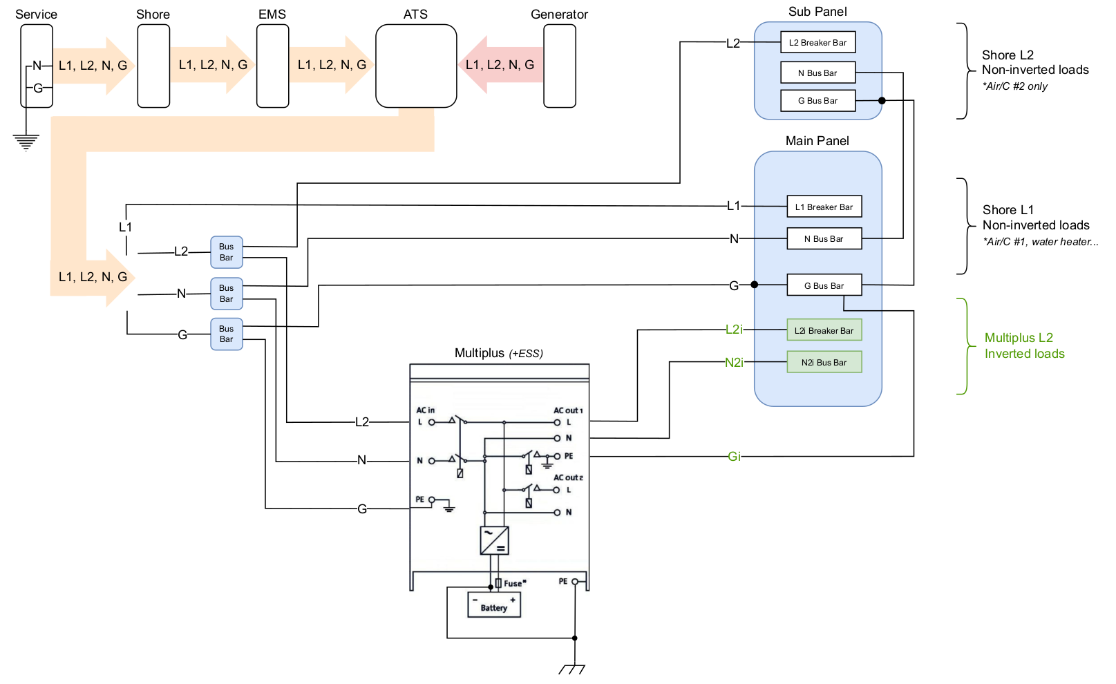
It's an increment on an existing system that has served us well for the last few years. Comments & observations welcome!