question

gregr avatar image
gregr asked

Redundant battery system optimized for shading

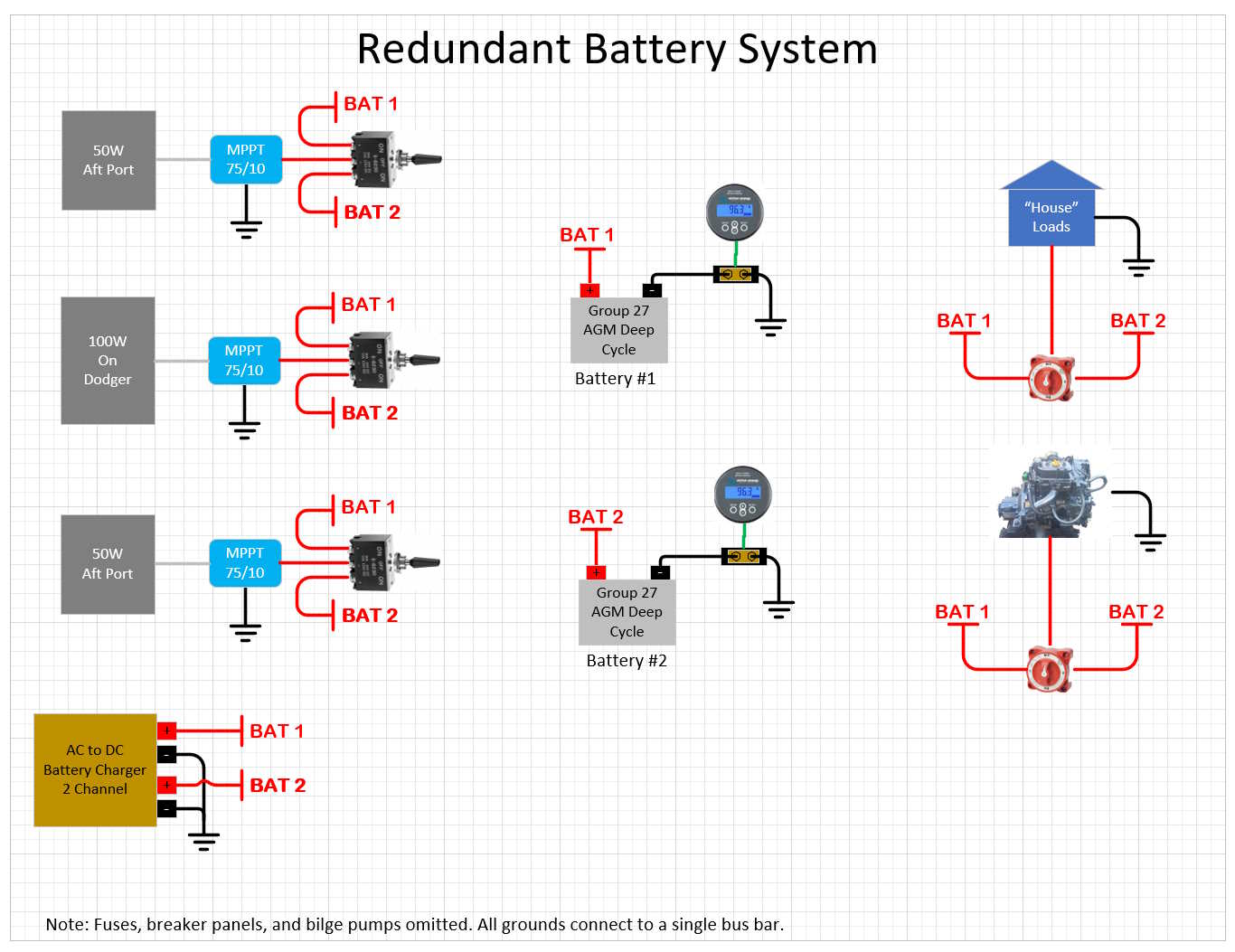
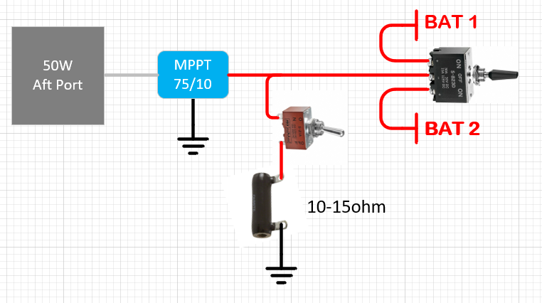
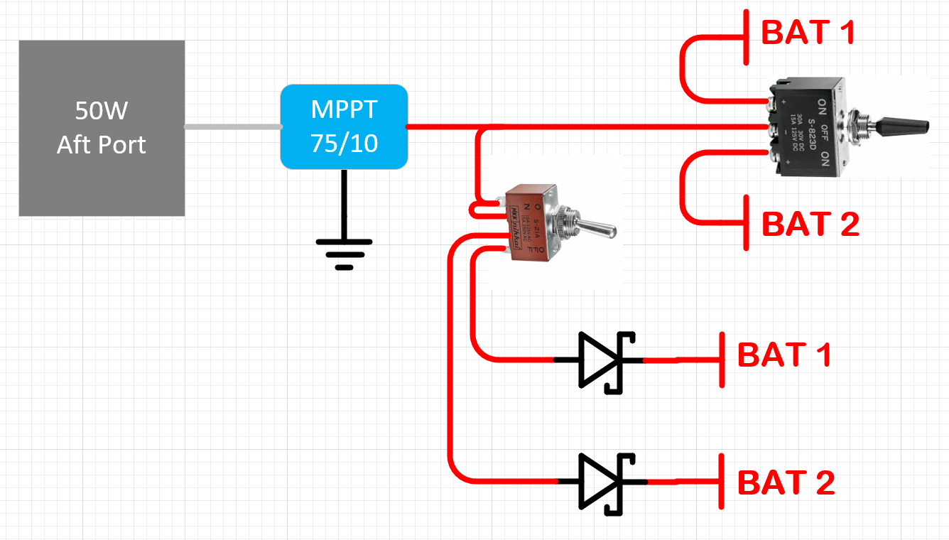
I'm in the process of setting up the system shown below. It's for a 30' sailboat. I expect significant shading so each panel gets its own mppt charger. The system is fully redundant when underway or at anchor. Can the controllers handle being hot swapped between batteries as shown. Or, do I need to add a switch between each panel an controller so I can disconnect the panel before switching the controller to the other battery?


Regards,

Greg

electrical-system-230731.jpg

MPPT Controllers
1 comment
2 |3000

Up to 8 attachments (including images) can be used with a maximum of 190.8 MiB each and 286.6 MiB total.

nesswill avatar image nesswill commented ·

You should try not to switch under load where the equipment is not designed to do so as it can cause oxidisation in contacts (over time) particular when the two contacting surfaces are of differing materials or the connection is not good (arcing, high resistance). I have seen a lot of equipment returned with contact oxidisation particular in areas of high humidity.

0 Likes 0 ·
8 Answers
mvas avatar image
mvas answered ·

Did you ask you local dealer / distributor with help designing your system?

1 comment
2 |3000

Up to 8 attachments (including images) can be used with a maximum of 190.8 MiB each and 286.6 MiB total.

gregr avatar image gregr commented ·
Hi Mvas,

No, my system is so small that I didn't want to waste a dealers time. It seems like a pretty simple, and I would have thought common, question. The site claims there are 90 folks following this thread. I'm hoping someone will chime in with some suggestions for something that will work given Ejrossouw was pretty adamant that my initial approach will damage the controllers. I appreciate that, it would have been a shame to burn up $300 in controllers.

Thanks for asking,

Greg


P.S. Requirements:

1. Redundant systems so a fault in one will not take out the other.

2. Optimized handling of shading.

0 Likes 0 ·
ejrossouw avatar image
ejrossouw answered ·

Worth reading the installation section of the manual. There is a specific sequence that has to be respected.1690869788093.png


1690869788093.png (110.9 KiB)
2 |3000

Up to 8 attachments (including images) can be used with a maximum of 190.8 MiB each and 286.6 MiB total.

gregr avatar image
gregr answered ·

Hi ejrossouw,

I guess it depends on which manual. This is from the manual for the 75/10 up to something like 100/20. It agrees with the order you list but doesn't say anything about delays and such.

1690875203950.png


I think I've seen responses to posts by Victron moderators that said switching was ok. The main issues I'm trying to address are keeping the system redundant and as tolerant of shading as possible. Most designs for boats use the house bank with a starter battery model. I can build a microcontroller and automotive relay system to achieve the sequence described. I'm hoping the controllers are robust enough to handle the hot swap. A system that requires that switches be flipped in a certain order is too easy to screw up.

Regards,

Greg


1690875203950.png (54.9 KiB)
1 comment
2 |3000

Up to 8 attachments (including images) can be used with a maximum of 190.8 MiB each and 286.6 MiB total.

ejrossouw avatar image ejrossouw commented ·
The devices are not designed for hotswap scenarios so you will invalidate any warranty doing so, but that you have to clarify with your Victron supplier. The MPPTs may well survive, but I have seen the terminal blocks typically fail given it is not intended to switch under load etc.
1 Like 1 ·
bigbadbob76 avatar image
bigbadbob76 answered ·

It is not a good idea to hot swap charge controllers between batteries but you could hot swap panels between charge controllers, ideally using solid state relays to avoid arcing.

Using two charge controllers, one per battery, and switching the least shaded panel to the battery you wish to charge might work for you.

if shading changes too frequently (yawing/tacking) for this then maybe having the two 50W panels in parallel permanently connected to one charge controller and the 100w one to the other might be your best plan.

1 comment
2 |3000

Up to 8 attachments (including images) can be used with a maximum of 190.8 MiB each and 286.6 MiB total.

gregr avatar image gregr commented ·

Hi Bob,

The open circuit voltage is less than 30V so arcing shouldn't be a major issue. Using solid state relays is an option but they don't provide 100% isolation, and they add a small vampire load.

Switching the panels is on my list of options. The downside is I have to train crew to deal with it if I'm off watch.

The 50s on one controller and the 100 on the other may be where I end up.

I did come up with the idea of using a 2 deck, 5 position rotary switch. One deck would control the MPPT and the second would control the PV. Rotating the switch from 1 to 5 creates the sequence that has been described.

1: MPPT connected to bat 1. PV connected

2. MPPT connected to bat 1. PV disconnected

3. MPPT disconnected. PV disconnected

4. MPPT connected to bat 2. PV disconnected

5. MPPT connected to bat 2. PV connected


One could expand it to a third deck and 7 positions:

1. MPPT connected to bat 1. PV connected. Load connected

2. MPPT connected to bat 1. PV connected. Load disconnected

3. MPPT connected to bat 1. PV disconnected. Load disconnected

4. MPPT disconnected. PV disconnected. Load disconnected

5. MPPT connected to bat 2. PV disconnected. Load disconnected

6. MPPT connected to bat 2. PV connected. Load disconnected

7. MPPT connected to bat 2. PV connected. Load connected

(Note: 3 decks and 7 positions might be a bit of a unicorn)


Regards,

Greg


0 Likes 0 ·
seb71 avatar image
seb71 answered ·

You make the system less reliable/worse if you do this.

Just put the batteries in parallel (or get a larger one, if you do not already have them) and you are done.

-------

Did you check that those small PV panels have high enough voltage? They might not charge at all.

The PV voltage needs to be at least 5V higher than the battery voltage (actual, not nominal).

1 comment
2 |3000

Up to 8 attachments (including images) can be used with a maximum of 190.8 MiB each and 286.6 MiB total.

gregr avatar image gregr commented ·
Hi Seb71,

We'll have to agree to disagree on this one. I don't dive with just one regulator. I don't set just one anchor when rock climbing. I don't think it wise to go offshore with only a single power system capable of handling the minimum loads.

I will be keeping my options open with respect to putting the 50W panels in series. Thanks for the heads up.

Regards,

Greg

0 Likes 0 ·
Alexandra avatar image
Alexandra answered ·

@GregR

You could always have an Orion DC to DC that you can use for charging Battery to battery.

Hot swapping is definitely not recommended. Proper shut down and switch over - yes, but definitely not under load.

@ejrossouw and @Bigbadbob76 and @Seb71 are correct, it will void warranty as well since it moves out of the intended install and use scenarios.

Besides being dangerous because of sparks and various contacts potentially failing.

For the 90% you are referring to, who say you can, just because there have been no consequences so far doesn't make it safe or right.

4 comments
2 |3000

Up to 8 attachments (including images) can be used with a maximum of 190.8 MiB each and 286.6 MiB total.

gregr avatar image gregr commented ·
Hi Alexandra,

Requirement 1 is redundant. Yes, I'm probably being paranoid but, I want two separate systems. Using an Orion still ties the two together.

Hot swap is out.

Components certainly need to be sized correctly. I'm new to solar but I'm engineer and have designed kW, redundant power systems that can be hot swapped. I just don't know what the Victron hardware can handle. The Renogy panels I'm looking at have an open circuit voltage that's less than 30V. A short circuit current of less than 6A. My loads add up to a few amps.

I didn't refer to 90%. I made a comment that there were 90 people following this thread.

I appreciate the response but please slow down and read what folks post more carefully before responding.

Regards,

Greg

0 Likes 0 ·
Alexandra avatar image Alexandra ♦ gregr commented ·

Hi Greg,

Of the 90 followers, it is likely alot are systen added since they follow a tag you used. Possibly not added manually by themselves.

My apologies about the 90% remark.

Hot swapping is a commom question with solar, and there many who argue it is ok when it is not. I have even had discussions with guys trying to hot swap 250VDC live pv arrays with relays.

My apologies, I still had the boxing gloves on from a previous conversation with a person who was being adamant something was ok when it isn't safe. Doing solar right is not cheap and not worth it unless you do it right.

An orion can be in place but only manually/switch activated. So yes still linked but only when you specifically want it to be.

Is the two channel battery charger able to charge each battery differently (multi bank multistage charger)? If the two batteries are totally separate what are the chances they will be at same SOC and one might need to be charged longer or shorter than the other? AGMs are fairly fussy about overcharge.

0 Likes 0 ·
gregr avatar image gregr Alexandra ♦ commented ·
Hi Alexandra,

No worries. I have those conversations with clients on a regular basis. I once had to do a write up to show why this guy's idea for a perpetual motion machine wouldn't work. He is a friend of one of the owners of the company...

The charger is a dual bank multistage charger. It will be disconnected when offshore and I'm looking at replacing it with two stand alone chargers.

I'll take a look at the Orion.

Thanks,

Greg

1 Like 1 ·
Alexandra avatar image Alexandra ♦ gregr commented ·

Lol. Ah a favorite topic.

I had one recently involving a pump to make a pretty waterfall with hydro to power lights (and said pump) on a pond ~also perpetual motion related~

Thank you for understanding.


Best regards


Alex

0 Likes 0 ·
gregr avatar image
gregr answered ·

So I've spent some more time thinking about this and it seems the controller output has to be current limited. I haven't seen anything saying you need to disconnect a controller from a battery that is used for starting. That output, in parallel with the battery, sees a load of several hundred amps when you press the start button. That suggests the issue is that the output doesn't handle going open circuit. Switching in a nominal load resistor, before switching batteries, should protect the controller so it doesn't see an open circuit condition.resistor-load.png

Temporarily switching in a pair of diodes should work as well. The switch of course needs to be rated for the full output of the charge controller.

diode-combiner.png

Both of these solutions require a switch sequence to avoid subjecting the controller to an open circuit but it means the system will automatically handle shading. The resistor approach maintains full isolation. The diode approach only connects the two for the second or two that it takes to switch between batteries and it doesn't support current flow between batteries.


Regards,

Greg


resistor-load.png (52.0 KiB)
diode-combiner.png (125.3 KiB)
2 |3000

Up to 8 attachments (including images) can be used with a maximum of 190.8 MiB each and 286.6 MiB total.

seb71 avatar image
seb71 answered ·

Or, do I need to add a switch between each panel an controller so I can disconnect the panel before switching the controller to the other battery?

Yous should have a PV disconnect switch (both PV wires) for each MPPT anyway (even for a system with one battery).

Also, all PV wires should be protected by fuses (gPV type).

2 |3000

Up to 8 attachments (including images) can be used with a maximum of 190.8 MiB each and 286.6 MiB total.